Cirkit Designer Logo
Cirkit Designer
Your all-in-one circuit design IDE
Home / 
Component Documentation

How to Use RGB: Examples, Pinouts, and Specs

Image of RGB
Cirkit Designer LogoDesign with RGB in Cirkit Designer

Introduction

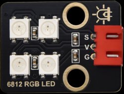
An RGB LED is a versatile electronic component that combines red, green, and blue light-emitting diodes in a single package. By adjusting the intensity of each color, it can produce a wide spectrum of colors, making it ideal for a variety of applications such as mood lighting, display panels, and decorative purposes. RGB LEDs are commonly used in electronics projects, including those involving microcontrollers like the Arduino UNO.

Explore Projects Built with RGB

Use Cirkit Designer to design, explore, and prototype these projects online. Some projects support real-time simulation. Click "Open Project" to start designing instantly!
Interactive RGB LED Control Circuit with Pushbuttons
Image of rgb circuit: A project utilizing RGB in a practical application
This circuit features a 9V battery connected to a voltage regulator, which likely steps down the voltage to a lower level suitable for driving an RGB LED. Three pushbuttons are connected to the output of the voltage regulator, each controlling one color channel (red, green, and blue) of the RGB LED. A resistor is connected in series with the common cathode of the RGB LED to limit the current through the LED.
Cirkit Designer LogoOpen Project in Cirkit Designer
Battery-Powered RGB LED Control with Pushbuttons
Image of EXP-12 E: A project utilizing RGB in a practical application
This circuit consists of an RGB LED controlled by three pushbuttons, each corresponding to one of the LED's color channels (Red, Green, and Blue). The pushbuttons are powered by a MAHIR 1.mini power source, allowing the user to manually toggle each color channel of the RGB LED.
Cirkit Designer LogoOpen Project in Cirkit Designer
Arduino Uno RGB LED Controller with TCS34725 Color Sensor
Image of RGB COLOR DETECTOR : A project utilizing RGB in a practical application
This circuit uses an Arduino Uno to control an RGB LED module and read color data from a TCS3472 color sensor. The Arduino processes the color data from the sensor and adjusts the RGB LED's color output accordingly, providing a visual representation of the detected colors.
Cirkit Designer LogoOpen Project in Cirkit Designer
Arduino Nano-Controlled Lighting System with Gesture and Sound Interaction
Image of 4 load controll using hand gesture and sound controll: A project utilizing RGB in a practical application
This circuit features an Arduino Nano microcontroller interfaced with an APDS-9960 RGB and Gesture Sensor for color and gesture detection, and a KY-038 microphone module for sound detection. The Arduino controls a 4-channel relay module, which in turn switches four AC bulbs on and off. The 12V power supply is used to power the relay module, and the bulbs are connected to the normally open (N.O.) contacts of the relays, allowing the Arduino to control the lighting based on sensor inputs.
Cirkit Designer LogoOpen Project in Cirkit Designer

Explore Projects Built with RGB

Use Cirkit Designer to design, explore, and prototype these projects online. Some projects support real-time simulation. Click "Open Project" to start designing instantly!
Image of rgb circuit: A project utilizing RGB in a practical application
Interactive RGB LED Control Circuit with Pushbuttons
This circuit features a 9V battery connected to a voltage regulator, which likely steps down the voltage to a lower level suitable for driving an RGB LED. Three pushbuttons are connected to the output of the voltage regulator, each controlling one color channel (red, green, and blue) of the RGB LED. A resistor is connected in series with the common cathode of the RGB LED to limit the current through the LED.
Cirkit Designer LogoOpen Project in Cirkit Designer
Image of EXP-12 E: A project utilizing RGB in a practical application
Battery-Powered RGB LED Control with Pushbuttons
This circuit consists of an RGB LED controlled by three pushbuttons, each corresponding to one of the LED's color channels (Red, Green, and Blue). The pushbuttons are powered by a MAHIR 1.mini power source, allowing the user to manually toggle each color channel of the RGB LED.
Cirkit Designer LogoOpen Project in Cirkit Designer
Image of RGB COLOR DETECTOR : A project utilizing RGB in a practical application
Arduino Uno RGB LED Controller with TCS34725 Color Sensor
This circuit uses an Arduino Uno to control an RGB LED module and read color data from a TCS3472 color sensor. The Arduino processes the color data from the sensor and adjusts the RGB LED's color output accordingly, providing a visual representation of the detected colors.
Cirkit Designer LogoOpen Project in Cirkit Designer
Image of 4 load controll using hand gesture and sound controll: A project utilizing RGB in a practical application
Arduino Nano-Controlled Lighting System with Gesture and Sound Interaction
This circuit features an Arduino Nano microcontroller interfaced with an APDS-9960 RGB and Gesture Sensor for color and gesture detection, and a KY-038 microphone module for sound detection. The Arduino controls a 4-channel relay module, which in turn switches four AC bulbs on and off. The 12V power supply is used to power the relay module, and the bulbs are connected to the normally open (N.O.) contacts of the relays, allowing the Arduino to control the lighting based on sensor inputs.
Cirkit Designer LogoOpen Project in Cirkit Designer

Technical Specifications

Key Technical Details

  • Forward Voltage: Typically 2.0V - 2.2V for red, 3.0V - 3.2V for green and blue
  • Forward Current: 20mA (per channel)
  • Luminous Intensity: Varies by color and manufacturer
  • Viewing Angle: Typically 120 degrees

Pin Configuration and Descriptions

Pin Number Color Description
1 Red Anode or cathode for the red LED segment
2 Common Common anode or cathode for all segments
3 Green Anode or cathode for the green LED segment
4 Blue Anode or cathode for the blue LED segment

Note: The common pin may be either an anode or cathode, depending on the type of RGB LED (common anode or common cathode).

Usage Instructions

Connecting an RGB LED to a Circuit

  1. Identify the Type: Determine if your RGB LED is common anode or common cathode.
  2. Resistor Selection: Choose appropriate resistors to limit current to each LED segment. Use Ohm's law (V = IR) to calculate the resistor value.
  3. Wiring: Connect the common pin to either VCC (for common anode) or GND (for common cathode). Connect each color pin through a resistor to a digital output pin on your microcontroller.
  4. Microcontroller Configuration: Configure the microcontroller pins as outputs.

Important Considerations and Best Practices

  • Current Limiting: Always use current-limiting resistors to prevent damage to the LED.
  • PWM Control: Use pulse-width modulation (PWM) to control the brightness of each color.
  • Heat Dissipation: Ensure proper heat dissipation if operating at high brightness levels for extended periods.

Example Code for Arduino UNO

// Define the RGB LED pins
const int RED_PIN = 9;    // Red LED pin
const int GREEN_PIN = 10; // Green LED pin
const int BLUE_PIN = 11;  // Blue LED pin

void setup() {
  // Set the LED pins as outputs
  pinMode(RED_PIN, OUTPUT);
  pinMode(GREEN_PIN, OUTPUT);
  pinMode(BLUE_PIN, OUTPUT);
}

void loop() {
  // Set the color to purple (red + blue)
  analogWrite(RED_PIN, 255);   // Red at full intensity
  analogWrite(GREEN_PIN, 0);   // Green off
  analogWrite(BLUE_PIN, 255);  // Blue at full intensity

  delay(1000); // Wait for 1 second

  // Set the color to aqua (green + blue)
  analogWrite(RED_PIN, 0);     // Red off
  analogWrite(GREEN_PIN, 255); // Green at full intensity
  analogWrite(BLUE_PIN, 255);  // Blue at full intensity

  delay(1000); // Wait for 1 second
}

Note: The above code assumes a common anode RGB LED. For a common cathode, invert the PWM values (use 255 - value).

Troubleshooting and FAQs

Common Issues

  • Dim or No Light: Ensure the resistors are correctly calculated and installed. Check for proper power supply voltage and ground connections.
  • Incorrect Colors: Verify that the pins are connected to the correct color anodes or cathodes. Adjust PWM values as needed.
  • Flickering: Ensure stable power supply and check for loose connections.

Solutions and Tips

  • Resistor Calculation: Use online LED resistor calculators for accurate resistor values.
  • PWM Frequency: If using PWM, ensure the frequency is high enough to avoid visible flicker.
  • Code Debugging: Use serial output to debug and verify that the correct PWM signals are being sent.

FAQs

Q: Can I connect an RGB LED directly to an Arduino without resistors? A: No, resistors are necessary to limit the current and prevent damage to both the LED and the Arduino.

Q: How do I create custom colors? A: Mix different intensities of red, green, and blue using the analogWrite() function to create custom colors.

Q: What is the difference between common anode and common cathode RGB LEDs? A: In common anode LEDs, all anodes are connected together to VCC. In common cathode LEDs, all cathodes are connected to GND. The type affects how you control the LED with your microcontroller.