
How to Use MPL115A1 / MPL115A2 Barometer (Family Diagram): Examples, Pinouts, and Specs
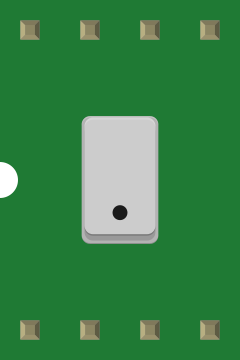
 Design with MPL115A1 / MPL115A2 Barometer (Family Diagram) in Cirkit Designer
Introduction
The MPL115A1 and MPL115A2 are digital barometric pressure sensors designed to provide accurate atmospheric pressure readings with built-in temperature compensation. These sensors are compact, low-power, and ideal for applications requiring precise pressure measurements. They communicate via an I²C or SPI interface, making them easy to integrate into microcontroller-based systems.
Explore Projects Built with MPL115A1 / MPL115A2 Barometer (Family Diagram)
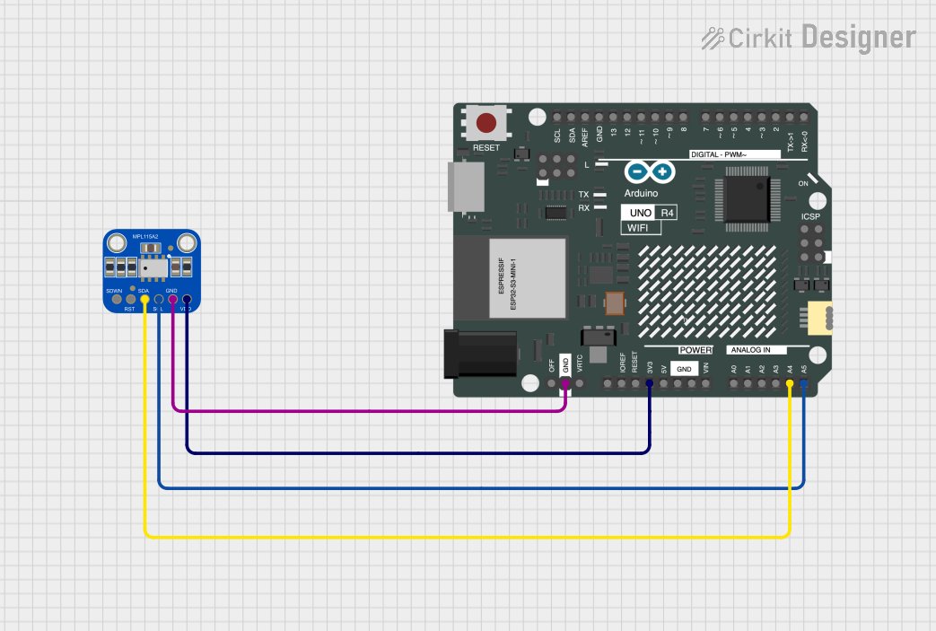 Open Project in Cirkit Designer
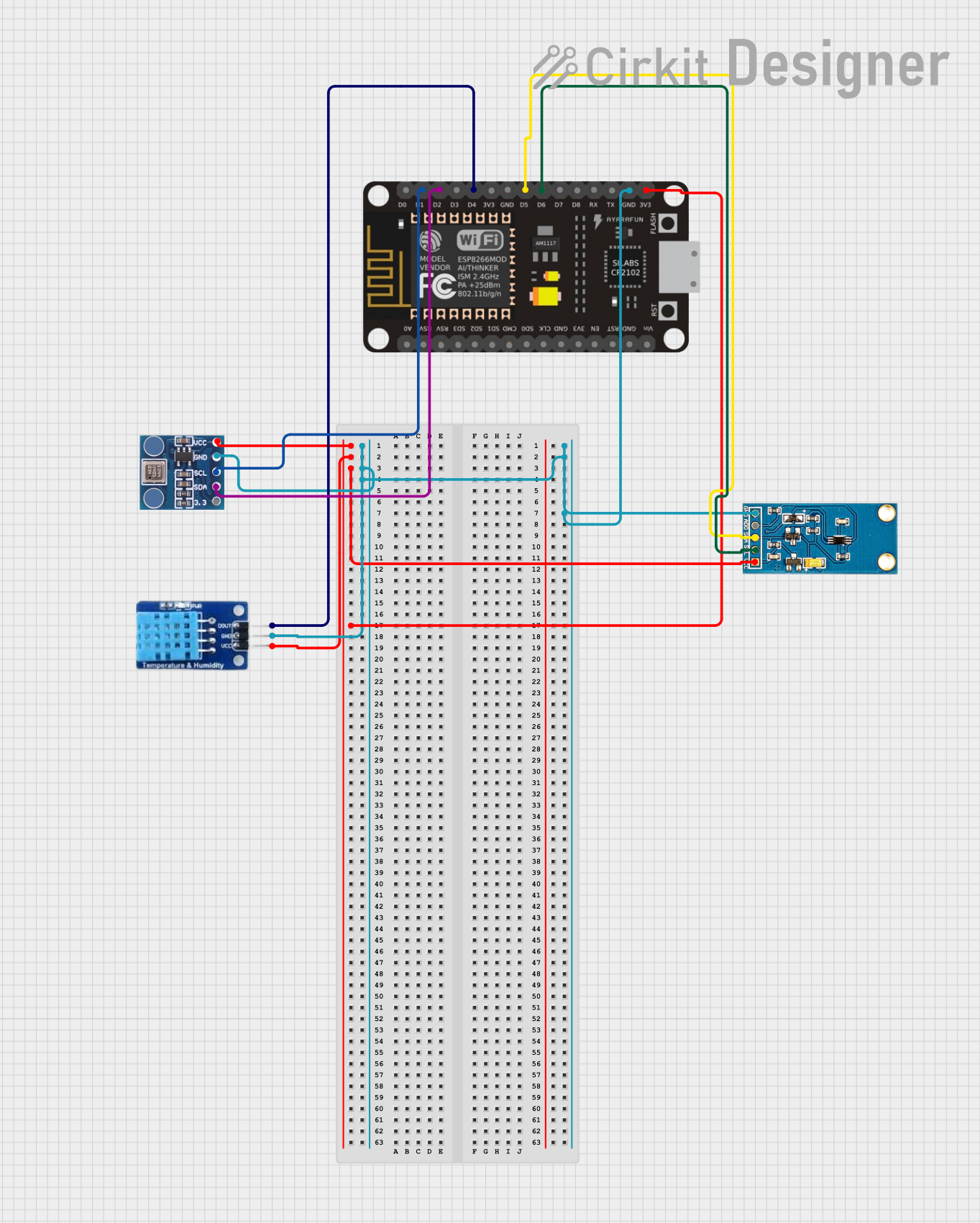 Open Project in Cirkit Designer
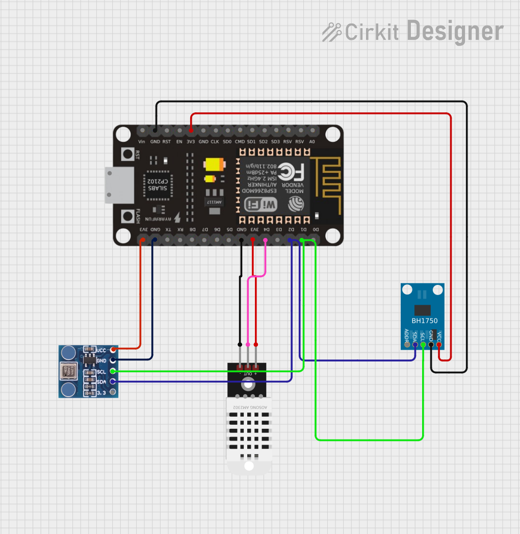 Open Project in Cirkit Designer
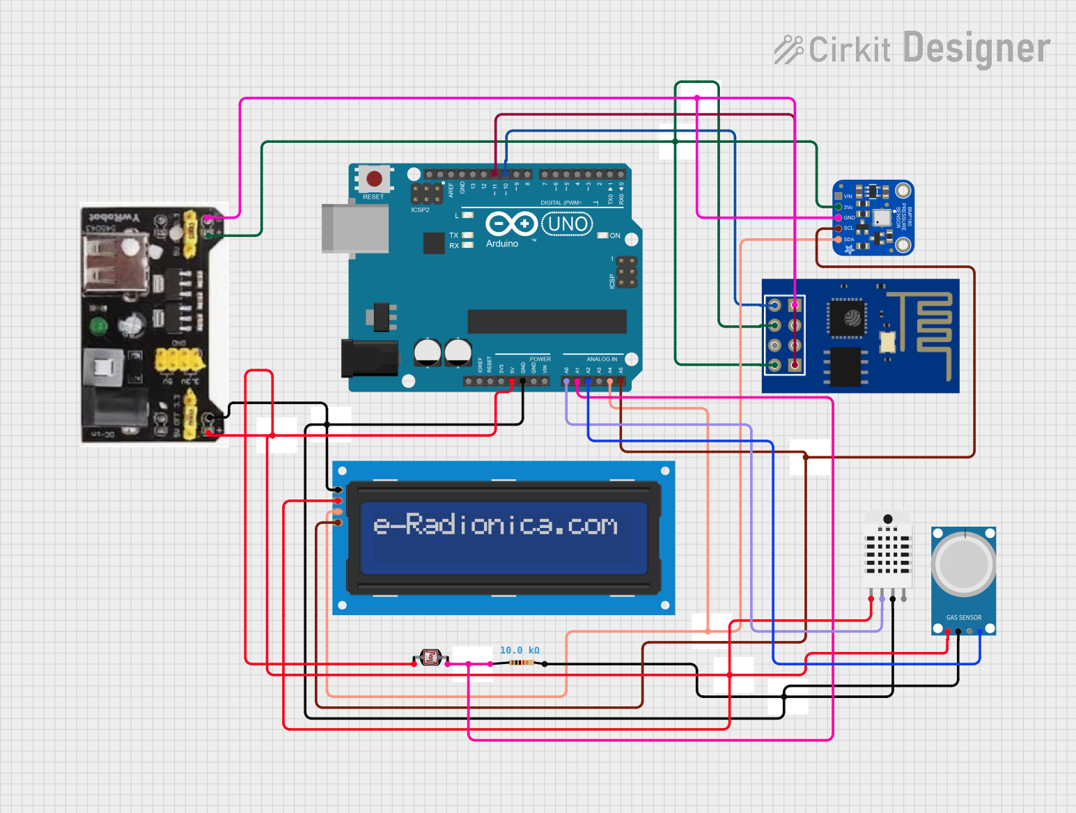 Open Project in Cirkit Designer
Explore Projects Built with MPL115A1 / MPL115A2 Barometer (Family Diagram)
Open Project in Cirkit DesignerOpen Project in Cirkit DesignerOpen Project in Cirkit DesignerOpen Project in Cirkit DesignerCommon Applications
- Weather stations
- Altimeters for drones and aircraft
- HVAC systems
- Portable weather monitoring devices
- Environmental data logging
Technical Specifications
Key Specifications
| Parameter | Value |
|---|---|
| Operating Voltage | 2.375V to 5.5V |
| Pressure Range | 50 kPa to 115 kPa |
| Pressure Accuracy | ±1 kPa |
| Temperature Compensation | Built-in |
| Communication Interface | I²C or SPI |
| Operating Temperature Range | -40°C to +85°C |
| Current Consumption | 5 µA (typical in standby mode) |
| Package Type | LGA (5 mm x 3 mm x 1.2 mm) |
Pin Configuration and Descriptions
MPL115A1 Pinout
| Pin Number | Pin Name | Description |
|---|---|---|
| 1 | VDD | Power supply (2.375V to 5.5V) |
| 2 | GND | Ground |
| 3 | SCL | I²C clock input |
| 4 | SDA | I²C data input/output |
| 5 | CSB | Chip select for SPI (active low) |
| 6 | SCLK | SPI clock input |
| 7 | SDI | SPI data input |
| 8 | SDO | SPI data output |
MPL115A2 Pinout
| Pin Number | Pin Name | Description |
|---|---|---|
| 1 | VDD | Power supply (2.375V to 5.5V) |
| 2 | GND | Ground |
| 3 | SCL | I²C clock input |
| 4 | SDA | I²C data input/output |
Usage Instructions
Using the MPL115A1/MPL115A2 in a Circuit
- Power Supply: Connect the VDD pin to a 3.3V or 5V power source and the GND pin to ground.
- Communication Interface:
- For I²C: Connect the SCL and SDA pins to the corresponding I²C pins on your microcontroller. Use pull-up resistors (typically 4.7 kΩ) on both lines.
- For SPI (MPL115A1 only): Connect the CSB, SCLK, SDI, and SDO pins to the corresponding SPI pins on your microcontroller.
- Bypass Capacitor: Place a 0.1 µF capacitor close to the VDD pin for power supply decoupling.
- Initialization: Configure the microcontroller to communicate with the sensor using the chosen interface.
Important Considerations
- Ensure the operating voltage matches the sensor's specifications.
- Use proper pull-up resistors for I²C communication.
- Avoid placing the sensor near heat sources to prevent inaccurate readings.
- Calibrate the sensor if required for your application.
Example Code for Arduino UNO (I²C)
#include <Wire.h>

// MPL115A2 I2C address
#define MPL115A2_ADDRESS 0x60

// Register addresses
#define PRESSURE_MSB 0x00
#define PRESSURE_LSB 0x01
#define TEMPERATURE_MSB 0x02
#define TEMPERATURE_LSB 0x03
#define START_CONVERSION 0x12

void setup() {
  Wire.begin(); // Initialize I2C communication
  Serial.begin(9600); // Start serial communication for debugging
}

void loop() {
  // Start pressure and temperature conversion
  Wire.beginTransmission(MPL115A2_ADDRESS);
  Wire.write(START_CONVERSION);
  Wire.endTransmission();
  delay(5); // Wait for conversion to complete

  // Read pressure and temperature data
  Wire.beginTransmission(MPL115A2_ADDRESS);
  Wire.write(PRESSURE_MSB);
  Wire.endTransmission();
  Wire.requestFrom(MPL115A2_ADDRESS, 4);

  if (Wire.available() == 4) {
    uint16_t pressure = (Wire.read() << 8) | Wire.read();
    uint16_t temperature = (Wire.read() << 8) | Wire.read();

    // Convert raw data to human-readable values
    float pressure_kPa = pressure / 64.0; // Example conversion
    float temperature_C = temperature / 64.0; // Example conversion

    // Print results
    Serial.print("Pressure (kPa): ");
    Serial.println(pressure_kPa);
    Serial.print("Temperature (°C): ");
    Serial.println(temperature_C);
  }

  delay(1000); // Wait 1 second before next reading
}
Troubleshooting and FAQs
Common Issues
No Data from Sensor:
- Ensure the sensor is powered correctly and the ground is connected.
- Verify the I²C or SPI connections and check for loose wires.
- Confirm the correct I²C address (default: 0x60) is being used.
Inaccurate Readings:
- Check for nearby heat sources that may affect temperature compensation.
- Ensure the sensor is not exposed to excessive moisture or contaminants.
- Verify the calibration coefficients if using custom calculations.
Communication Errors:
- Ensure pull-up resistors are present on the I²C lines.
- Check the SPI clock speed and ensure it is within the sensor's specifications.
FAQs
Q: Can the MPL115A1/MPL115A2 measure altitude?
A: Yes, by calculating the difference between the measured pressure and the standard sea-level pressure, you can estimate altitude.
Q: What is the difference between MPL115A1 and MPL115A2?
A: The MPL115A1 supports both I²C and SPI communication, while the MPL115A2 supports only I²C.
Q: Do I need to calibrate the sensor?
A: The sensor comes pre-calibrated, but you can perform additional calibration for higher accuracy in specific applications.
Q: Can I use this sensor with a 5V microcontroller?
A: Yes, the sensor supports operating voltages up to 5.5V, making it compatible with 5V systems like Arduino UNO.