The 12.8V 30000mAh 3C 4S5P LiFePO4 Battery Pack (Manufacturer: Pro-Range, Part ID: IFR 32650) is a high-performance rechargeable lithium iron phosphate (LiFePO4) battery pack. It features a nominal voltage of 12.8V, a capacity of 30,000mAh, and a discharge rate of 3C. The pack is constructed using 4 cells in series (4S) and 5 cells in parallel (5P), ensuring high energy density, long cycle life, and enhanced safety.
Explore Projects Built with 12.8V 30000mAh 3C 4S5P LiFePO4 Battery Pack
Use Cirkit Designer to design, explore, and prototype these projects online. Some projects support real-time simulation. Click "Open Project" to start designing instantly!
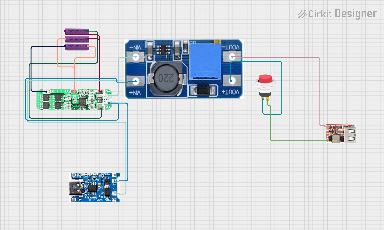
This circuit is a battery management and power supply system that uses three 3.7V batteries connected to a 3S 10A Li-ion 18650 Charger Protection Board Module for balanced charging and protection. The system includes a TP4056 Battery Charging Protection Module for additional charging safety, a Step Up Boost Power Converter to regulate and boost the voltage, and a USB regulator to provide a stable 5V output, controlled by a push switch.
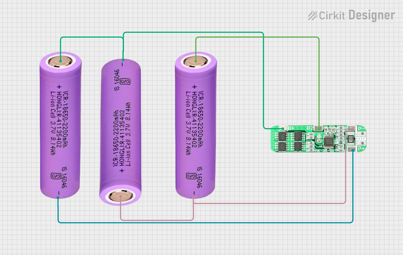
This circuit consists of three 18650 batteries connected in series to a 3S 10A Li-ion 18650 Charger Protection Board Module. The protection board manages the charging and discharging of the battery pack, ensuring safe operation by balancing the cells and providing overcharge, over-discharge, and short-circuit protection.
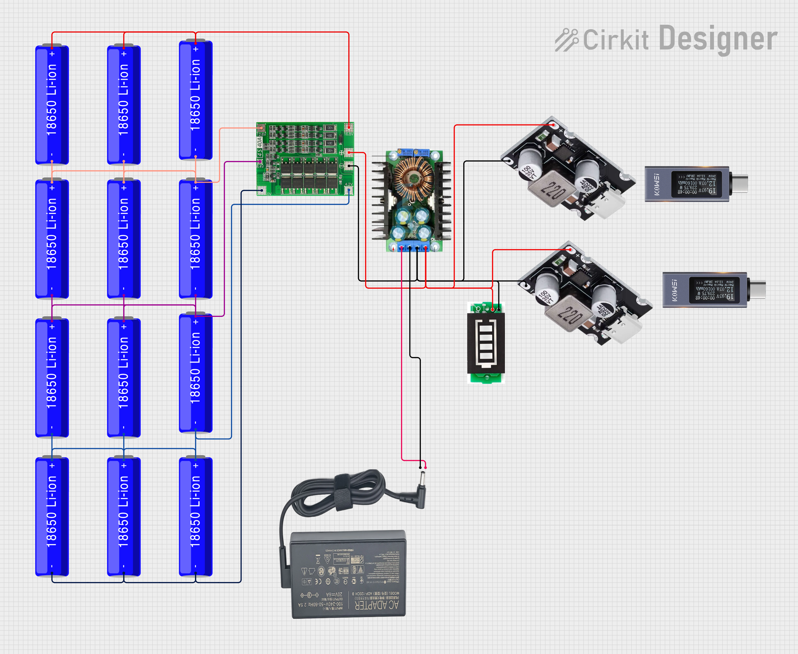
This circuit is a battery management and charging system for a 4S Li-ion battery pack. It includes multiple 18650 Li-ion batteries connected to a 4S40A BMS for balancing and protection, a battery indicator for monitoring charge status, and an XL4016 module for voltage regulation. The system is designed to be charged via a 20V input from a charger.
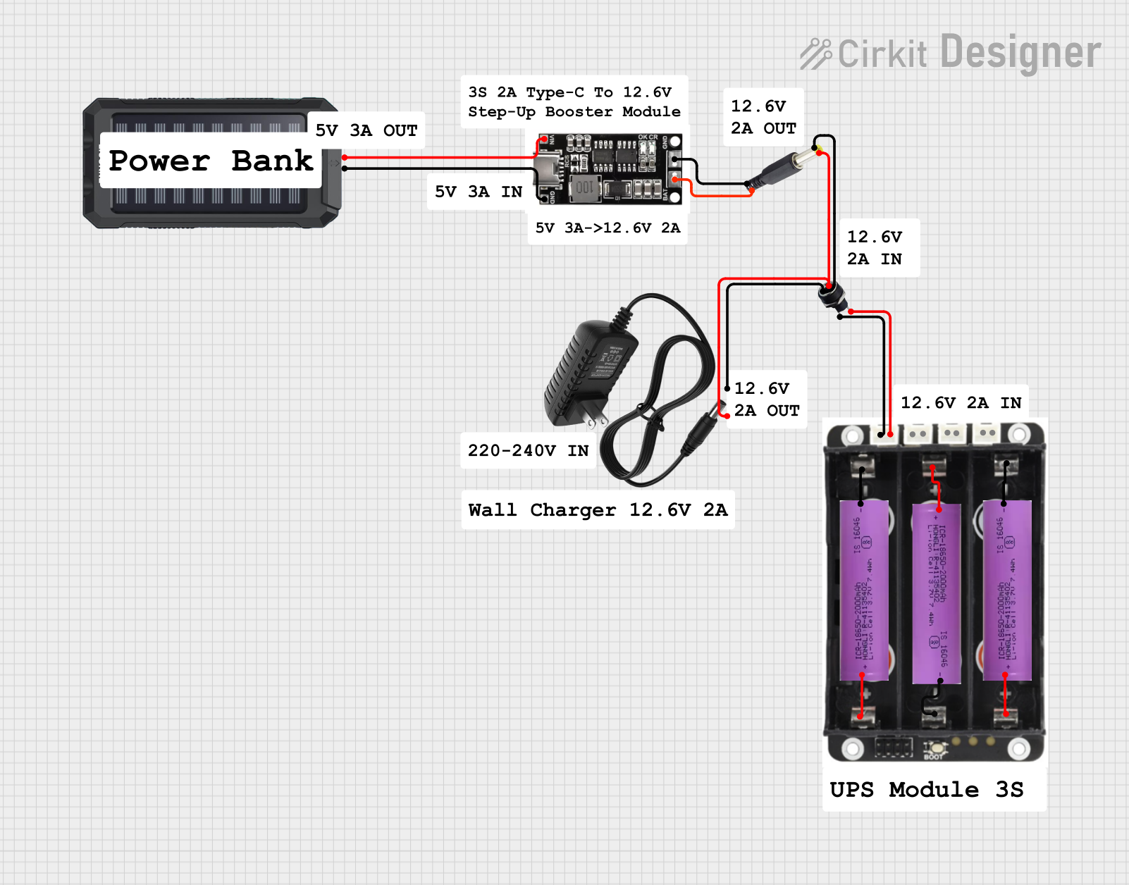
This circuit is a power management system that integrates a 12V power supply, a solar charger power bank, and multiple Li-ion batteries to provide a stable power output. The Waveshare UPS 3S manages the input from the power sources and batteries, ensuring continuous power delivery. The MRB045 module is used to interface the solar charger with the rest of the system.
The battery pack typically includes the following terminals and connections:
Pin/Terminal
Description
Positive (+)
Positive terminal for power output
Negative (-)
Negative terminal for power output
BMS Port
Connection to the Battery Management System (BMS) for monitoring and protection
Balance Leads
Leads for cell balancing during charging
Note: The exact pin configuration may vary depending on the specific design of the battery pack. Always refer to the manufacturer's datasheet for detailed wiring diagrams.
Usage Instructions
How to Use the Component in a Circuit
Connection to Load:
Connect the positive (+) and negative (-) terminals of the battery pack to the load or device.
Ensure the load does not exceed the maximum continuous discharge current (90A).
Charging the Battery:
Use a LiFePO4-compatible charger with a maximum charge voltage of 14.6V.
Ensure the charger supports the required charge current (e.g., 0.5C or 15A for optimal charging).
Battery Management System (BMS):
The battery pack includes a built-in BMS for overcharge, over-discharge, and short-circuit protection.
Connect the BMS port to a compatible monitoring system if required.
Cell Balancing:
During charging, the BMS ensures cell balancing to maintain consistent voltage across all cells.
Important Considerations and Best Practices
Avoid Overcharging: Do not exceed the maximum charge voltage of 14.6V to prevent damage.
Avoid Deep Discharge: Do not discharge below the cut-off voltage of 10.0V to extend cycle life.
Temperature Management: Operate the battery within the specified temperature range to ensure safety and performance.
Storage: Store the battery at 50% charge in a cool, dry place if not in use for extended periods.
Wiring: Use appropriately rated wires and connectors to handle the high current output.
Example: Connecting to an Arduino UNO
The battery pack can power an Arduino UNO via a DC-DC step-down converter to regulate the voltage to 5V. Below is an example circuit and code:
Circuit Diagram
Connect the battery pack's positive (+) and negative (-) terminals to the input of a DC-DC step-down converter.
Set the output of the converter to 5V.
Connect the 5V output to the Arduino UNO's 5V and GND pins.
Arduino Code Example
// Example code to blink an LED using Arduino UNO powered by the LiFePO4 battery pack

const int ledPin = 13; // Pin connected to the onboard LED

void setup() {
  pinMode(ledPin, OUTPUT); // Set the LED pin as an output
}

void loop() {
  digitalWrite(ledPin, HIGH); // Turn the LED on
  delay(1000); // Wait for 1 second
  digitalWrite(ledPin, LOW); // Turn the LED off
  delay(1000); // Wait for 1 second
}
Note: Ensure the DC-DC converter is properly configured to output 5V before connecting to the Arduino UNO.
Troubleshooting and FAQs
Common Issues and Solutions
Issue
Possible Cause
Solution
Battery not charging
Charger not compatible or faulty
Use a LiFePO4-compatible charger
Low runtime
Over-discharge or aging cells
Avoid deep discharge; replace if aged
Overheating during use
Exceeding maximum discharge current
Reduce load or use a higher-capacity pack
Uneven cell voltages
Faulty BMS or cell imbalance
Check BMS; ensure proper balancing
FAQs
Can I use this battery pack for solar energy storage?
Yes, the battery pack is ideal for solar energy systems due to its long cycle life and stable performance.
What happens if I overcharge the battery?
The built-in BMS prevents overcharging, but using a compatible charger is essential to avoid damage.
How do I extend the battery's lifespan?
Avoid deep discharges, overcharging, and operating outside the recommended temperature range.
Can I connect multiple packs in series or parallel?
Yes, but ensure proper balancing and use a compatible BMS for series/parallel configurations.
By following these guidelines, you can safely and effectively use the 12.8V 30000mAh 3C 4S5P LiFePO4 Battery Pack in your projects.


 Open Project in Cirkit Designer