How to Use GDK 101: Examples, Pinouts, and Specs
Introduction
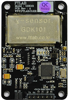
The GDK 101, manufactured by FTLab, is a versatile general-purpose development kit designed for prototyping and testing electronic circuits. It features a microcontroller, multiple input/output interfaces, and support for various communication protocols, making it an ideal choice for embedded systems development. The GDK 101 is suitable for hobbyists, students, and professionals working on projects ranging from IoT devices to industrial automation.
Explore Projects Built with GDK 101

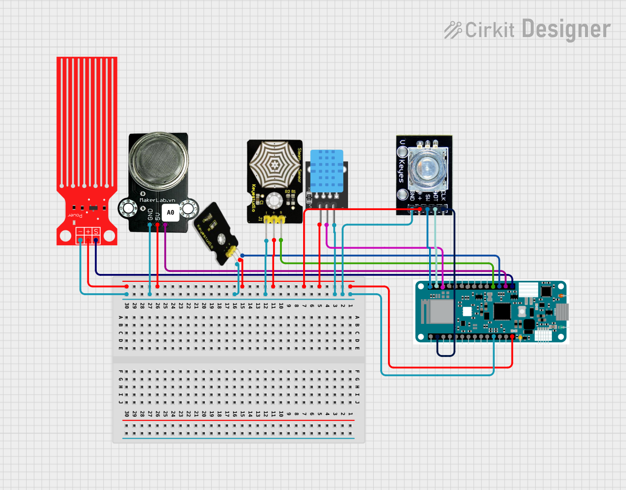

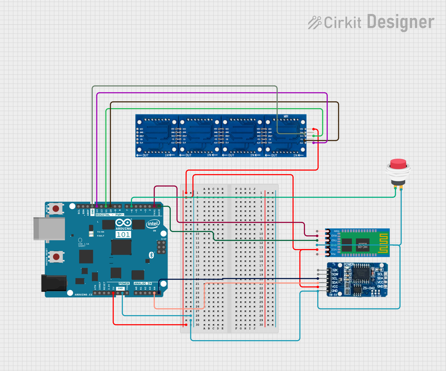
Explore Projects Built with GDK 101
Common Applications and Use Cases
- Rapid prototyping of embedded systems
- IoT device development
- Educational projects and learning microcontroller programming
- Industrial automation and control systems
- Sensor interfacing and data acquisition
Technical Specifications
The GDK 101 is equipped with a powerful microcontroller and a variety of interfaces to support diverse applications. Below are the key technical details:
General Specifications
| Parameter | Value |
|---|---|
| Microcontroller | ARM Cortex-M4 (32-bit) |
| Operating Voltage | 3.3V |
| Input Voltage Range | 5V via USB or 7-12V via VIN |
| Clock Speed | 72 MHz |
| Flash Memory | 256 KB |
| SRAM | 64 KB |
| Communication Protocols | UART, SPI, I2C, CAN, USB |
| GPIO Pins | 20 |
| ADC Resolution | 12-bit |
| PWM Channels | 6 |
| Dimensions | 70mm x 50mm |
Pin Configuration and Descriptions
The GDK 101 features a 20-pin GPIO header with the following pinout:
| Pin Number | Pin Name | Description |
|---|---|---|
| 1 | GND | Ground |
| 2 | 3.3V | 3.3V Power Output |
| 3 | 5V | 5V Power Output |
| 4 | VIN | External Power Input (7-12V) |
| 5 | A0 | Analog Input 0 |
| 6 | A1 | Analog Input 1 |
| 7 | A2 | Analog Input 2 |
| 8 | A3 | Analog Input 3 |
| 9 | D0 | Digital I/O 0 (UART RX) |
| 10 | D1 | Digital I/O 1 (UART TX) |
| 11 | D2 | Digital I/O 2 |
| 12 | D3 | Digital I/O 3 (PWM) |
| 13 | D4 | Digital I/O 4 |
| 14 | D5 | Digital I/O 5 (PWM) |
| 15 | D6 | Digital I/O 6 (PWM) |
| 16 | D7 | Digital I/O 7 |
| 17 | SCL | I2C Clock Line |
| 18 | SDA | I2C Data Line |
| 19 | MOSI | SPI Master Out Slave In |
| 20 | MISO | SPI Master In Slave Out |
Usage Instructions
The GDK 101 is designed to be user-friendly and can be easily integrated into various projects. Below are the steps and best practices for using the GDK 101:
How to Use the GDK 101 in a Circuit
Powering the Board:
- Connect the GDK 101 to a computer via USB for 5V power.
- Alternatively, use an external power supply (7-12V) connected to the VIN pin.
Programming the Microcontroller:
- Use an IDE such as Arduino IDE or Keil uVision to write and upload code.
- Select the appropriate board and port in the IDE settings.
Connecting Peripherals:
- Use the GPIO pins to connect sensors, actuators, or other peripherals.
- Ensure that the voltage and current requirements of the peripherals are compatible with the GDK 101.
Communication Protocols:
- Use UART, SPI, or I2C for communication with external devices.
- Refer to the pin configuration table for the correct pins.
Important Considerations and Best Practices
- Avoid exceeding the maximum voltage and current ratings of the pins to prevent damage.
- Use pull-up or pull-down resistors for stable digital input signals.
- For analog inputs, ensure the input voltage does not exceed 3.3V.
- Use decoupling capacitors near power pins to reduce noise in the circuit.
Example: Connecting to an Arduino UNO
The GDK 101 can be used as a peripheral device with an Arduino UNO. Below is an example of interfacing the GDK 101 via I2C:
#include <Wire.h> // Include the Wire library for I2C communication

#define GDK101_ADDRESS 0x42 // Replace with the actual I2C address of the GDK 101

void setup() {
  Wire.begin(); // Initialize I2C communication
  Serial.begin(9600); // Initialize serial communication for debugging

  Serial.println("Initializing GDK 101...");
}

void loop() {
  Wire.beginTransmission(GDK101_ADDRESS); // Start communication with GDK 101
  Wire.write(0x01); // Example command to request data
  Wire.endTransmission();

  delay(100); // Wait for the GDK 101 to process the request

  Wire.requestFrom(GDK101_ADDRESS, 2); // Request 2 bytes of data
  if (Wire.available() == 2) {
    int data = Wire.read() << 8 | Wire.read(); // Read and combine the two bytes
    Serial.print("Received data: ");
    Serial.println(data);
  } else {
    Serial.println("No data received from GDK 101.");
  }

  delay(1000); // Wait before the next request
}
Troubleshooting and FAQs
Common Issues and Solutions
The GDK 101 is not powering on:
- Ensure the USB cable or external power supply is properly connected.
- Check that the input voltage is within the specified range (5V via USB or 7-12V via VIN).
Unable to upload code to the microcontroller:
- Verify that the correct board and port are selected in the IDE.
- Ensure the USB driver for the GDK 101 is installed on your computer.
Peripherals are not responding:
- Double-check the wiring and connections to the GPIO pins.
- Confirm that the peripheral's voltage and current requirements are compatible with the GDK 101.
I2C communication is not working:
- Ensure the correct I2C address is used in the code.
- Use pull-up resistors (typically 4.7kΩ) on the SDA and SCL lines.
FAQs
Can the GDK 101 be powered by batteries?
Yes, the GDK 101 can be powered by a battery pack providing 7-12V connected to the VIN pin.What IDEs are compatible with the GDK 101?
The GDK 101 is compatible with popular IDEs such as Arduino IDE, Keil uVision, and PlatformIO.Does the GDK 101 support wireless communication?
No, the GDK 101 does not have built-in wireless communication. However, external modules like Wi-Fi or Bluetooth can be connected via UART or SPI.
This concludes the documentation for the GDK 101. For further assistance, refer to the official FTLab user manual or contact their support team.