Cirkit Designer Logo
Cirkit Designer
Your all-in-one circuit design IDE
Home / 
Component Documentation

How to Use RGB LED: Examples, Pinouts, and Specs

Image of RGB LED
Cirkit Designer LogoDesign with RGB LED in Cirkit Designer

Introduction

An RGB LED is a versatile electronic component that combines red, green, and blue light-emitting diodes to produce a wide spectrum of colors. By adjusting the intensity of each individual color, it can create various hues and shades, making it popular in decorative lighting, signal indicators, and display panels. RGB LEDs are commonly used in electronics projects, including those involving microcontrollers like the Arduino UNO.

Explore Projects Built with RGB LED

Use Cirkit Designer to design, explore, and prototype these projects online. Some projects support real-time simulation. Click "Open Project" to start designing instantly!
Battery-Powered RGB LED Control with Pushbuttons
Image of EXP-12 E: A project utilizing RGB LED in a practical application
This circuit consists of an RGB LED controlled by three pushbuttons, each corresponding to one of the LED's color channels (Red, Green, and Blue). The pushbuttons are powered by a MAHIR 1.mini power source, allowing the user to manually toggle each color channel of the RGB LED.
Cirkit Designer LogoOpen Project in Cirkit Designer
ESP32-Controlled RGB LED Lighting System
Image of RGBLEDwithFlutterFirebase: A project utilizing RGB LED in a practical application
This circuit features an ESP32 microcontroller connected to an RGB LED through three 200 Ohm resistors. Each color channel (Red, Green, Blue) of the LED is connected to a GPIO pin (G13, G12, G14 respectively) on the ESP32 via a resistor. The common anode of the RGB LED is directly connected to the 3.3V power supply from the ESP32, allowing the microcontroller to control the color of the LED by PWM signals on the GPIO pins.
Cirkit Designer LogoOpen Project in Cirkit Designer
Interactive RGB LED Control Circuit with Pushbuttons
Image of rgb circuit: A project utilizing RGB LED in a practical application
This circuit features a 9V battery connected to a voltage regulator, which likely steps down the voltage to a lower level suitable for driving an RGB LED. Three pushbuttons are connected to the output of the voltage regulator, each controlling one color channel (red, green, and blue) of the RGB LED. A resistor is connected in series with the common cathode of the RGB LED to limit the current through the LED.
Cirkit Designer LogoOpen Project in Cirkit Designer
ESP32 Wi-Fi Controlled RGB LED Light
Image of rgb_led: A project utilizing RGB LED in a practical application
This circuit uses an ESP32 microcontroller to control an RGB LED through three 330-ohm resistors connected to the GPIO pins. The ESP32 provides power to the common pin of the RGB LED and controls the red, green, and blue channels individually to create various colors.
Cirkit Designer LogoOpen Project in Cirkit Designer

Explore Projects Built with RGB LED

Use Cirkit Designer to design, explore, and prototype these projects online. Some projects support real-time simulation. Click "Open Project" to start designing instantly!
Image of EXP-12 E: A project utilizing RGB LED in a practical application
Battery-Powered RGB LED Control with Pushbuttons
This circuit consists of an RGB LED controlled by three pushbuttons, each corresponding to one of the LED's color channels (Red, Green, and Blue). The pushbuttons are powered by a MAHIR 1.mini power source, allowing the user to manually toggle each color channel of the RGB LED.
Cirkit Designer LogoOpen Project in Cirkit Designer
Image of RGBLEDwithFlutterFirebase: A project utilizing RGB LED in a practical application
ESP32-Controlled RGB LED Lighting System
This circuit features an ESP32 microcontroller connected to an RGB LED through three 200 Ohm resistors. Each color channel (Red, Green, Blue) of the LED is connected to a GPIO pin (G13, G12, G14 respectively) on the ESP32 via a resistor. The common anode of the RGB LED is directly connected to the 3.3V power supply from the ESP32, allowing the microcontroller to control the color of the LED by PWM signals on the GPIO pins.
Cirkit Designer LogoOpen Project in Cirkit Designer
Image of rgb circuit: A project utilizing RGB LED in a practical application
Interactive RGB LED Control Circuit with Pushbuttons
This circuit features a 9V battery connected to a voltage regulator, which likely steps down the voltage to a lower level suitable for driving an RGB LED. Three pushbuttons are connected to the output of the voltage regulator, each controlling one color channel (red, green, and blue) of the RGB LED. A resistor is connected in series with the common cathode of the RGB LED to limit the current through the LED.
Cirkit Designer LogoOpen Project in Cirkit Designer
Image of rgb_led: A project utilizing RGB LED in a practical application
ESP32 Wi-Fi Controlled RGB LED Light
This circuit uses an ESP32 microcontroller to control an RGB LED through three 330-ohm resistors connected to the GPIO pins. The ESP32 provides power to the common pin of the RGB LED and controls the red, green, and blue channels individually to create various colors.
Cirkit Designer LogoOpen Project in Cirkit Designer

Technical Specifications

Key Technical Details

  • Forward Voltage (Typical): Red: 2.0-2.2V, Green: 3.0-3.2V, Blue: 3.0-3.2V
  • Forward Current: 20mA (per channel)
  • Luminous Intensity: Varies by color and manufacturer
  • Viewing Angle: Typically 120 degrees

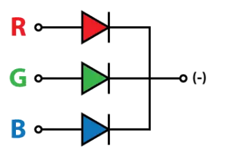
Pin Configuration and Descriptions

Pin Number Description Common Type
1 Red Anode/Cathode Anode/Cathode
2 Green Anode/Cathode Anode/Cathode
3 Blue Anode/Cathode Anode/Cathode
4 Common Cathode/Anode Cathode/Anode

Note: The common pin is either the common anode or common cathode, depending on the type of RGB LED.

Usage Instructions

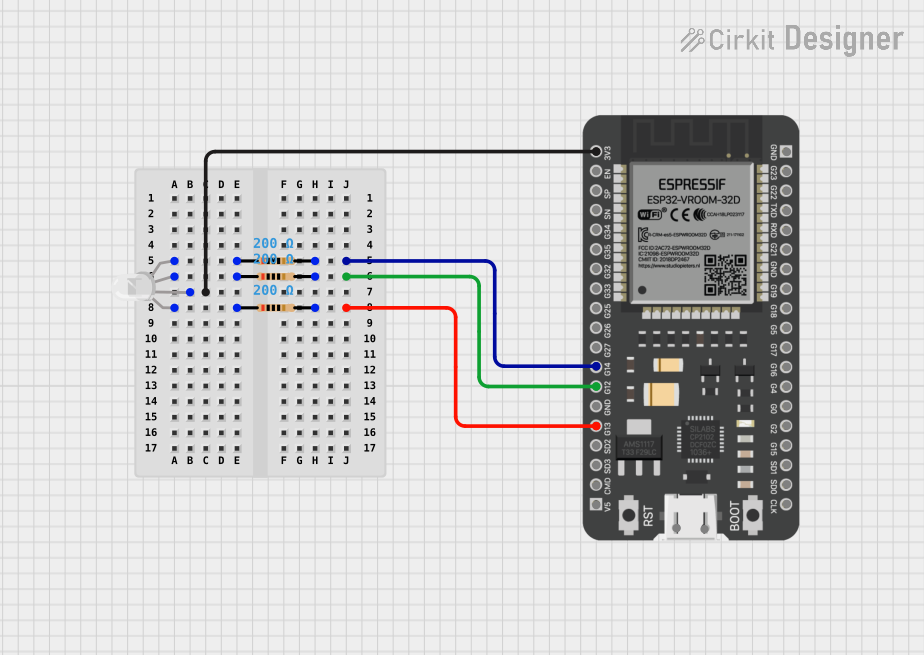
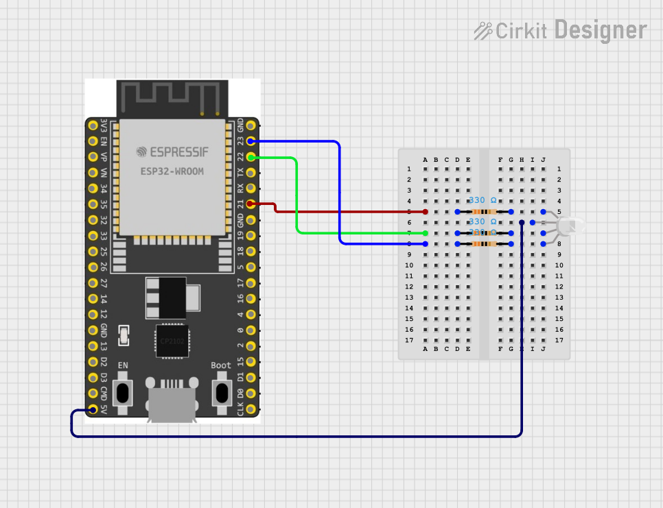
Connecting to a Circuit

  1. Identify the Type: Determine if your RGB LED is common anode or common cathode.
  2. Current Limiting Resistors: Connect a current-limiting resistor in series with each anode/cathode of the red, green, and blue LEDs. Calculate the resistor value using Ohm's law: R = (V_supply - V_LED) / I_LED.
  3. Wiring to Arduino: Connect the common pin to either GND (common cathode) or 5V (common anode). Connect the other pins to PWM-capable digital pins on the Arduino.

Best Practices

  • Use pulse-width modulation (PWM) to control the brightness of each color.
  • Avoid exceeding the maximum forward current to prevent damage.
  • Use resistors to prevent excessive current through the LEDs.

Example Code for Arduino UNO

// Define the RGB LED pins
const int RED_PIN = 9;    // Red pin connected to digital pin 9
const int GREEN_PIN = 10; // Green pin connected to digital pin 10
const int BLUE_PIN = 11;  // Blue pin connected to digital pin 11

void setup() {
  // Set the RGB LED pins as output
  pinMode(RED_PIN, OUTPUT);
  pinMode(GREEN_PIN, OUTPUT);
  pinMode(BLUE_PIN, OUTPUT);
}

void loop() {
  // Set the color to purple (Red + Blue)
  analogWrite(RED_PIN, 255);   // Red at full intensity
  analogWrite(GREEN_PIN, 0);   // Green off
  analogWrite(BLUE_PIN, 255);  // Blue at full intensity
  
  delay(1000); // Wait for 1 second
  
  // Set the color to aqua (Green + Blue)
  analogWrite(RED_PIN, 0);     // Red off
  analogWrite(GREEN_PIN, 255); // Green at full intensity
  analogWrite(BLUE_PIN, 255);  // Blue at full intensity
  
  delay(1000); // Wait for 1 second
}

Note: The above code assumes a common anode RGB LED. For a common cathode, set the pins to LOW to turn on the LED.

Troubleshooting and FAQs

Common Issues

  • LED Not Lighting Up: Ensure the common pin is correctly connected to 5V (common anode) or GND (common cathode). Check the polarity of the individual LED pins.
  • Incorrect Colors: Verify that the correct pins are connected to the corresponding color channels on the Arduino.
  • Dim LED: Confirm that the current-limiting resistors are of the correct value and that the Arduino's PWM function is working properly.

Solutions and Tips

  • Double-check wiring and pin assignments.
  • Use a multimeter to verify the voltage across the LED pins.
  • Ensure that the PWM values in the code match the desired color mix.

FAQs

Q: Can I connect an RGB LED directly to an Arduino without resistors? A: No, you should always use current-limiting resistors to prevent damaging the LED and the Arduino.

Q: How do I produce white light with an RGB LED? A: Set the PWM values for red, green, and blue to full brightness to mix the colors into white.

Q: What is PWM and how does it control the LED brightness? A: PWM stands for Pulse-Width Modulation. It controls the brightness by varying the duty cycle of the power supplied to the LED.