Cirkit Designer Logo
Cirkit Designer
Your all-in-one circuit design IDE
Home / 
Component Documentation

How to Use gy-neo6mv2_ww: Examples, Pinouts, and Specs

Image of gy-neo6mv2_ww
Cirkit Designer LogoDesign with gy-neo6mv2_ww in Cirkit Designer

Introduction

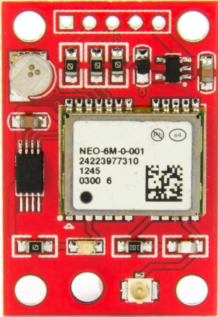
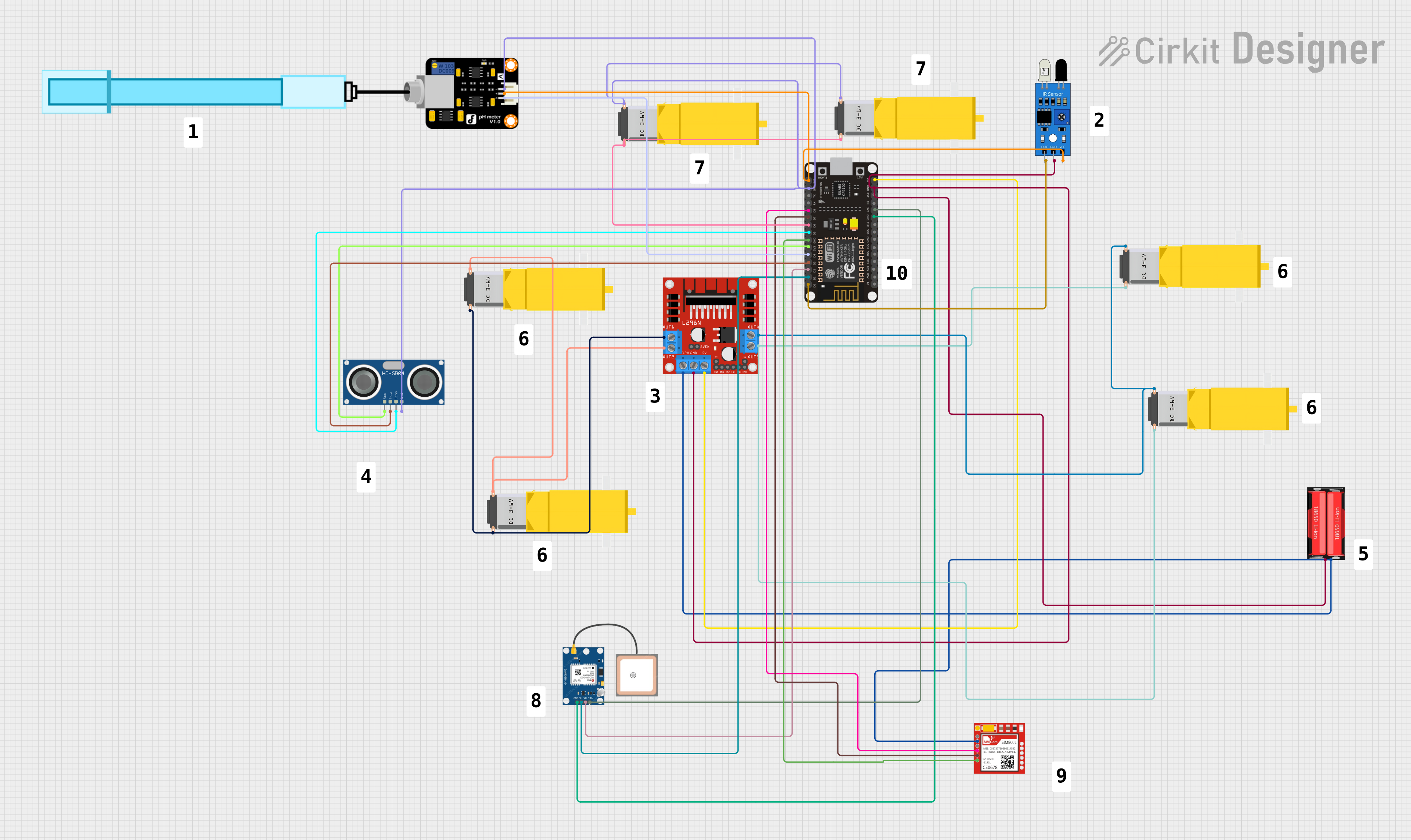
The GY-NEO6MV2 is a GPS module that provides accurate positioning data. It features the NEO-6M GPS chip and includes an onboard antenna, making it suitable for various navigation and tracking applications. This module is widely used in projects requiring precise location information, such as drones, vehicle tracking systems, and outdoor navigation devices.

Explore Projects Built with gy-neo6mv2_ww

Use Cirkit Designer to design, explore, and prototype these projects online. Some projects support real-time simulation. Click "Open Project" to start designing instantly!
Arduino UNO Based Quadcopter Control System with GPS, MPU6050, and Ultrasonic Sensor
Image of Virtual Drone: A project utilizing gy-neo6mv2_ww in a practical application
This circuit features an Arduino UNO microcontroller interfaced with a NEO-6M GPS module, an MPU6050 accelerometer/gyroscope, an HC-SR04 ultrasonic sensor, an OV7725 camera module, and a FLYSKY FS-IA6 receiver. It controls four brushless motors through electronic speed controllers (ESCs), which are powered by a 12V battery. The ESCs receive control signals from the Arduino, which likely processes input from the sensors and receiver to adjust the motor speeds, suggesting this could be part of a drone or a similar remotely controlled vehicle.
Cirkit Designer LogoOpen Project in Cirkit Designer
Location-Aware IoT Device with GSM Communication and LED Indicators
Image of LEDBikeVest-CircuitDiagram: A project utilizing gy-neo6mv2_ww in a practical application
This circuit features an Arduino Nano for GSM communication and GPS tracking, and a Wemos D1 Mini for controlling WS2812 RGB LED strips. It includes motion sensing with an MPU-6050 and is powered by Li-ion batteries with TP4056 charging modules. The microcontrollers' code is not yet implemented.
Cirkit Designer LogoOpen Project in Cirkit Designer
Gesture-Controlled Wheelchair with Arduino UNO, Arduino Nano, and HC-05 Bluetooth Modules
Image of Gesture Control Wheelchair: A project utilizing gy-neo6mv2_ww in a practical application
This circuit features an Arduino Nano interfaced with an InvenSense MPU6050 accelerometer/gyroscope for motion sensing and an HC-05 Bluetooth module for wireless communication. The Arduino Nano processes the MPU6050 data to interpret gestures and sends corresponding commands via Bluetooth. Additionally, an Arduino UNO is connected to an L298N motor driver to control two DC motors, receiving commands from a separate HC-05 module, likely for remote maneuvering of a vehicle or robotic platform.
Cirkit Designer LogoOpen Project in Cirkit Designer
ESP8266 Controlled Robotics Platform with GPS, IR, and GSM Features
Image of IOT based Trash Collecting Vessel: A project utilizing gy-neo6mv2_ww in a practical application
This is a microcontroller-based control system designed for a mobile robotic platform with environmental sensing, location tracking, and GSM communication capabilities. It includes motor control for actuation, various sensors for data acquisition, and a battery for power supply.
Cirkit Designer LogoOpen Project in Cirkit Designer

Explore Projects Built with gy-neo6mv2_ww

Use Cirkit Designer to design, explore, and prototype these projects online. Some projects support real-time simulation. Click "Open Project" to start designing instantly!
Image of Virtual Drone: A project utilizing gy-neo6mv2_ww in a practical application
Arduino UNO Based Quadcopter Control System with GPS, MPU6050, and Ultrasonic Sensor
This circuit features an Arduino UNO microcontroller interfaced with a NEO-6M GPS module, an MPU6050 accelerometer/gyroscope, an HC-SR04 ultrasonic sensor, an OV7725 camera module, and a FLYSKY FS-IA6 receiver. It controls four brushless motors through electronic speed controllers (ESCs), which are powered by a 12V battery. The ESCs receive control signals from the Arduino, which likely processes input from the sensors and receiver to adjust the motor speeds, suggesting this could be part of a drone or a similar remotely controlled vehicle.
Cirkit Designer LogoOpen Project in Cirkit Designer
Image of LEDBikeVest-CircuitDiagram: A project utilizing gy-neo6mv2_ww in a practical application
Location-Aware IoT Device with GSM Communication and LED Indicators
This circuit features an Arduino Nano for GSM communication and GPS tracking, and a Wemos D1 Mini for controlling WS2812 RGB LED strips. It includes motion sensing with an MPU-6050 and is powered by Li-ion batteries with TP4056 charging modules. The microcontrollers' code is not yet implemented.
Cirkit Designer LogoOpen Project in Cirkit Designer
Image of Gesture Control Wheelchair: A project utilizing gy-neo6mv2_ww in a practical application
Gesture-Controlled Wheelchair with Arduino UNO, Arduino Nano, and HC-05 Bluetooth Modules
This circuit features an Arduino Nano interfaced with an InvenSense MPU6050 accelerometer/gyroscope for motion sensing and an HC-05 Bluetooth module for wireless communication. The Arduino Nano processes the MPU6050 data to interpret gestures and sends corresponding commands via Bluetooth. Additionally, an Arduino UNO is connected to an L298N motor driver to control two DC motors, receiving commands from a separate HC-05 module, likely for remote maneuvering of a vehicle or robotic platform.
Cirkit Designer LogoOpen Project in Cirkit Designer
Image of IOT based Trash Collecting Vessel: A project utilizing gy-neo6mv2_ww in a practical application
ESP8266 Controlled Robotics Platform with GPS, IR, and GSM Features
This is a microcontroller-based control system designed for a mobile robotic platform with environmental sensing, location tracking, and GSM communication capabilities. It includes motor control for actuation, various sensors for data acquisition, and a battery for power supply.
Cirkit Designer LogoOpen Project in Cirkit Designer

Technical Specifications

Key Technical Details

Parameter Value
GPS Chip NEO-6M
Operating Voltage 3.3V - 5V
Current Consumption 45mA (typical)
Position Accuracy 2.5m CEP
Update Rate 1Hz (default), up to 5Hz
Communication UART
Antenna Onboard
Dimensions 25mm x 35mm

Pin Configuration and Descriptions

Pin Name Description
1 VCC Power supply (3.3V - 5V)
2 GND Ground
3 TX Transmit data (UART)
4 RX Receive data (UART)
5 PPS Pulse per second (time pulse, optional)

Usage Instructions

How to Use the Component in a Circuit

  1. Power Supply: Connect the VCC pin to a 3.3V or 5V power supply and the GND pin to the ground.
  2. UART Communication: Connect the TX pin of the GPS module to the RX pin of your microcontroller (e.g., Arduino UNO) and the RX pin of the GPS module to the TX pin of your microcontroller.
  3. Optional PPS Pin: If you need precise timing information, connect the PPS pin to a digital input on your microcontroller.

Important Considerations and Best Practices

  • Antenna Placement: Ensure the onboard antenna has a clear view of the sky for optimal satellite reception.
  • Power Supply: Use a stable power supply to avoid fluctuations that could affect the GPS module's performance.
  • Baud Rate: The default baud rate for the NEO-6M GPS module is 9600. Ensure your microcontroller's UART is set to the same baud rate.

Example Code for Arduino UNO

#include <SoftwareSerial.h>
#include <TinyGPS++.h>

// Create a SoftwareSerial object for communication with the GPS module
SoftwareSerial ss(4, 3); // RX, TX

// Create a TinyGPS++ object
TinyGPSPlus gps;

void setup() {
  Serial.begin(9600); // Initialize serial communication with the computer
  ss.begin(9600);     // Initialize serial communication with the GPS module
  Serial.println("GPS Module Test");
}

void loop() {
  while (ss.available() > 0) {
    gps.encode(ss.read()); // Decode the data from the GPS module

    if (gps.location.isUpdated()) {
      // Print the latitude and longitude to the Serial Monitor
      Serial.print("Latitude: ");
      Serial.println(gps.location.lat(), 6);
      Serial.print("Longitude: ");
      Serial.println(gps.location.lng(), 6);
    }
  }
}

Troubleshooting and FAQs

Common Issues Users Might Face

  1. No GPS Fix: The module is not able to get a GPS fix.

    • Solution: Ensure the antenna has a clear view of the sky. Move the module to an open area if necessary.
  2. No Data Output: The module is not sending any data.

    • Solution: Check the power connections and ensure the module is powered correctly. Verify the UART connections and baud rate settings.
  3. Inaccurate Positioning: The position data is not accurate.

    • Solution: Ensure the antenna is placed correctly and there are no obstructions. Wait for a few minutes to get a stable fix.

Solutions and Tips for Troubleshooting

  • Check Connections: Ensure all connections are secure and correct.
  • Verify Baud Rate: Make sure the baud rate of the GPS module matches the baud rate set in your microcontroller code.
  • Use a Stable Power Supply: Fluctuations in power supply can affect the performance of the GPS module.

By following this documentation, users should be able to effectively integrate and utilize the GY-NEO6MV2 GPS module in their projects. Whether you are a beginner or an experienced user, this guide provides the necessary information to get started and troubleshoot common issues.