Cirkit Designer Logo
Cirkit Designer
Your all-in-one circuit design IDE
Home / 
Component Documentation

How to Use Ultra-Small Size DC-DC 5V 3A BEC Power Supply Buck Step Down Module: Examples, Pinouts, and Specs

Image of Ultra-Small Size DC-DC 5V 3A BEC Power Supply Buck Step Down Module
Cirkit Designer LogoDesign with Ultra-Small Size DC-DC 5V 3A BEC Power Supply Buck Step Down Module in Cirkit Designer

Introduction

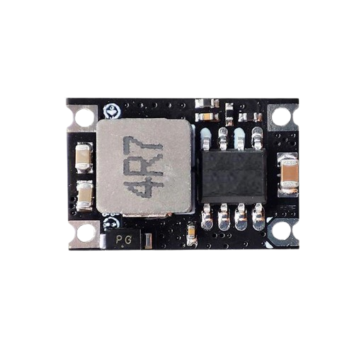
The Ultra-Small Size DC-DC 5V 3A BEC Power Supply Buck Step Down Module by Robu is a compact and efficient DC-DC converter designed to step down a higher input voltage to a stable 5V output. With a maximum current output of 3A, this module is ideal for powering low-voltage devices such as microcontrollers, sensors, and other electronic components. Its small size and high efficiency make it suitable for space-constrained applications.

Explore Projects Built with Ultra-Small Size DC-DC 5V 3A BEC Power Supply Buck Step Down Module

Use Cirkit Designer to design, explore, and prototype these projects online. Some projects support real-time simulation. Click "Open Project" to start designing instantly!
Battery-Powered 18650 Li-ion Charger with USB Output and Adjustable Voltage Regulator
Image of Breadboard: A project utilizing Ultra-Small Size DC-DC 5V 3A BEC Power Supply Buck Step Down Module in a practical application
This circuit is a battery management and power supply system that uses three 3.7V batteries connected to a 3S 10A Li-ion 18650 Charger Protection Board Module for balanced charging and protection. The system includes a TP4056 Battery Charging Protection Module for additional charging safety, a Step Up Boost Power Converter to regulate and boost the voltage, and a USB regulator to provide a stable 5V output, controlled by a push switch.
Cirkit Designer LogoOpen Project in Cirkit Designer
Battery-Powered Arduino UNO and ESP-8266 Smart Controller with LCD and RTC
Image of Ogie Diagram: A project utilizing Ultra-Small Size DC-DC 5V 3A BEC Power Supply Buck Step Down Module in a practical application
This circuit is a power management and control system that uses a 12V power supply and a 18650 Li-ion battery pack to provide a stable 5V output through a step-down buck converter. It includes an Arduino UNO, an ESP-8266 controller, a DS1307 RTC module, and a 20x4 I2C LCD display for monitoring and control purposes. The ULN2003A breakout board is used for driving higher current loads.
Cirkit Designer LogoOpen Project in Cirkit Designer
Battery-Powered UPS with Step-Down Buck Converter and BMS
Image of Mini ups: A project utilizing Ultra-Small Size DC-DC 5V 3A BEC Power Supply Buck Step Down Module in a practical application
This circuit is a power management system that steps down a 240V AC input to a lower DC voltage using a buck converter, which then powers a 40W UPS. The UPS is controlled by a rocker switch and is backed up by a battery management system (BMS) connected to three 3.7V batteries in series, ensuring continuous power supply.
Cirkit Designer LogoOpen Project in Cirkit Designer
USB Power Supply with Overcurrent Protection
Image of USB Charging port: A project utilizing Ultra-Small Size DC-DC 5V 3A BEC Power Supply Buck Step Down Module in a practical application
This circuit is designed to step down voltage from a 12V battery to a lower voltage suitable for USB devices. It includes a buck converter connected to the battery through a fuse and fuse holder for overcurrent protection. The output of the buck converter is connected to a USB female port, providing a regulated power supply for USB-powered devices.
Cirkit Designer LogoOpen Project in Cirkit Designer

Explore Projects Built with Ultra-Small Size DC-DC 5V 3A BEC Power Supply Buck Step Down Module

Use Cirkit Designer to design, explore, and prototype these projects online. Some projects support real-time simulation. Click "Open Project" to start designing instantly!
Image of Breadboard: A project utilizing Ultra-Small Size DC-DC 5V 3A BEC Power Supply Buck Step Down Module in a practical application
Battery-Powered 18650 Li-ion Charger with USB Output and Adjustable Voltage Regulator
This circuit is a battery management and power supply system that uses three 3.7V batteries connected to a 3S 10A Li-ion 18650 Charger Protection Board Module for balanced charging and protection. The system includes a TP4056 Battery Charging Protection Module for additional charging safety, a Step Up Boost Power Converter to regulate and boost the voltage, and a USB regulator to provide a stable 5V output, controlled by a push switch.
Cirkit Designer LogoOpen Project in Cirkit Designer
Image of Ogie Diagram: A project utilizing Ultra-Small Size DC-DC 5V 3A BEC Power Supply Buck Step Down Module in a practical application
Battery-Powered Arduino UNO and ESP-8266 Smart Controller with LCD and RTC
This circuit is a power management and control system that uses a 12V power supply and a 18650 Li-ion battery pack to provide a stable 5V output through a step-down buck converter. It includes an Arduino UNO, an ESP-8266 controller, a DS1307 RTC module, and a 20x4 I2C LCD display for monitoring and control purposes. The ULN2003A breakout board is used for driving higher current loads.
Cirkit Designer LogoOpen Project in Cirkit Designer
Image of Mini ups: A project utilizing Ultra-Small Size DC-DC 5V 3A BEC Power Supply Buck Step Down Module in a practical application
Battery-Powered UPS with Step-Down Buck Converter and BMS
This circuit is a power management system that steps down a 240V AC input to a lower DC voltage using a buck converter, which then powers a 40W UPS. The UPS is controlled by a rocker switch and is backed up by a battery management system (BMS) connected to three 3.7V batteries in series, ensuring continuous power supply.
Cirkit Designer LogoOpen Project in Cirkit Designer
Image of USB Charging port: A project utilizing Ultra-Small Size DC-DC 5V 3A BEC Power Supply Buck Step Down Module in a practical application
USB Power Supply with Overcurrent Protection
This circuit is designed to step down voltage from a 12V battery to a lower voltage suitable for USB devices. It includes a buck converter connected to the battery through a fuse and fuse holder for overcurrent protection. The output of the buck converter is connected to a USB female port, providing a regulated power supply for USB-powered devices.
Cirkit Designer LogoOpen Project in Cirkit Designer

Common Applications

  • Powering microcontrollers (e.g., Arduino, Raspberry Pi, ESP32)
  • Robotics and drones
  • Battery-powered devices
  • Portable electronics
  • IoT devices and sensors

Technical Specifications

Below are the key technical details of the module:

Parameter Value
Input Voltage Range 6V to 26V
Output Voltage 5V (fixed)
Maximum Output Current 3A
Efficiency Up to 92%
Dimensions 22mm x 17mm x 4mm
Weight ~3g
Operating Temperature -40°C to +85°C

Pin Configuration and Descriptions

The module has three pins for input and output connections:

Pin Name Description
VIN Input voltage (6V to 26V)
GND Ground (common for input and output)
VOUT Regulated 5V output

Usage Instructions

How to Use the Module in a Circuit

  1. Connect Input Voltage:

    • Connect the positive terminal of your power source (6V to 26V) to the VIN pin.
    • Connect the negative terminal of your power source to the GND pin.
  2. Connect Output Load:

    • Connect the device or circuit requiring 5V to the VOUT pin.
    • Ensure the GND pin is also connected to the ground of your load.
  3. Verify Connections:

    • Double-check all connections to avoid reverse polarity or short circuits.
  4. Power On:

    • Turn on the power source. The module will regulate the input voltage to a stable 5V output.

Important Considerations and Best Practices

  • Input Voltage Range: Ensure the input voltage is within the specified range (6V to 26V). Exceeding this range may damage the module.
  • Heat Dissipation: At higher currents (close to 3A), the module may generate heat. Use proper ventilation or a heatsink if necessary.
  • Polarity Protection: The module does not have built-in reverse polarity protection. Double-check the polarity of your connections.
  • Load Requirements: Ensure the connected load does not exceed the maximum output current of 3A.

Example: Using with Arduino UNO

The module can be used to power an Arduino UNO from a 12V battery. Below is an example circuit and code:

Circuit Connections

  • Connect the VIN pin of the module to the positive terminal of the 12V battery.
  • Connect the GND pin of the module to the negative terminal of the battery.
  • Connect the VOUT pin of the module to the 5V pin of the Arduino UNO.
  • Connect the GND pin of the module to the GND pin of the Arduino UNO.

Example Code

// Example code to blink an LED connected to pin 13 of Arduino UNO
// Ensure the Arduino is powered via the 5V output of the DC-DC module

void setup() {
  pinMode(13, OUTPUT); // Set pin 13 as an output
}

void loop() {
  digitalWrite(13, HIGH); // Turn the LED on
  delay(1000);            // Wait for 1 second
  digitalWrite(13, LOW);  // Turn the LED off
  delay(1000);            // Wait for 1 second
}

Troubleshooting and FAQs

Common Issues and Solutions

  1. No Output Voltage:

    • Cause: Incorrect input voltage or loose connections.
    • Solution: Verify that the input voltage is within the 6V to 26V range and check all connections.
  2. Overheating:

    • Cause: Excessive current draw or poor ventilation.
    • Solution: Ensure the load does not exceed 3A. Use a heatsink or improve airflow around the module.
  3. Output Voltage Not Stable:

    • Cause: Input voltage fluctuations or insufficient input power.
    • Solution: Use a stable power source and ensure the input voltage is at least 1V higher than the output voltage.
  4. Module Not Working After Connection:

    • Cause: Reverse polarity or short circuit.
    • Solution: Check the polarity of the input connections. Replace the module if it is damaged.

FAQs

Q1: Can this module be used to power a Raspberry Pi?
A1: Yes, the module can power a Raspberry Pi, but ensure the current draw does not exceed 3A.

Q2: Does the module have overcurrent protection?
A2: No, the module does not have built-in overcurrent protection. Use an external fuse if necessary.

Q3: Can I adjust the output voltage?
A3: No, the output voltage is fixed at 5V and cannot be adjusted.

Q4: Is the module suitable for automotive applications?
A4: Yes, as long as the input voltage is within the specified range and proper precautions are taken for heat dissipation.