How to Use Raspberry Pi Pico H Upside Down: Examples, Pinouts, and Specs
Introduction
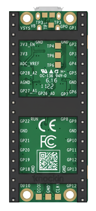
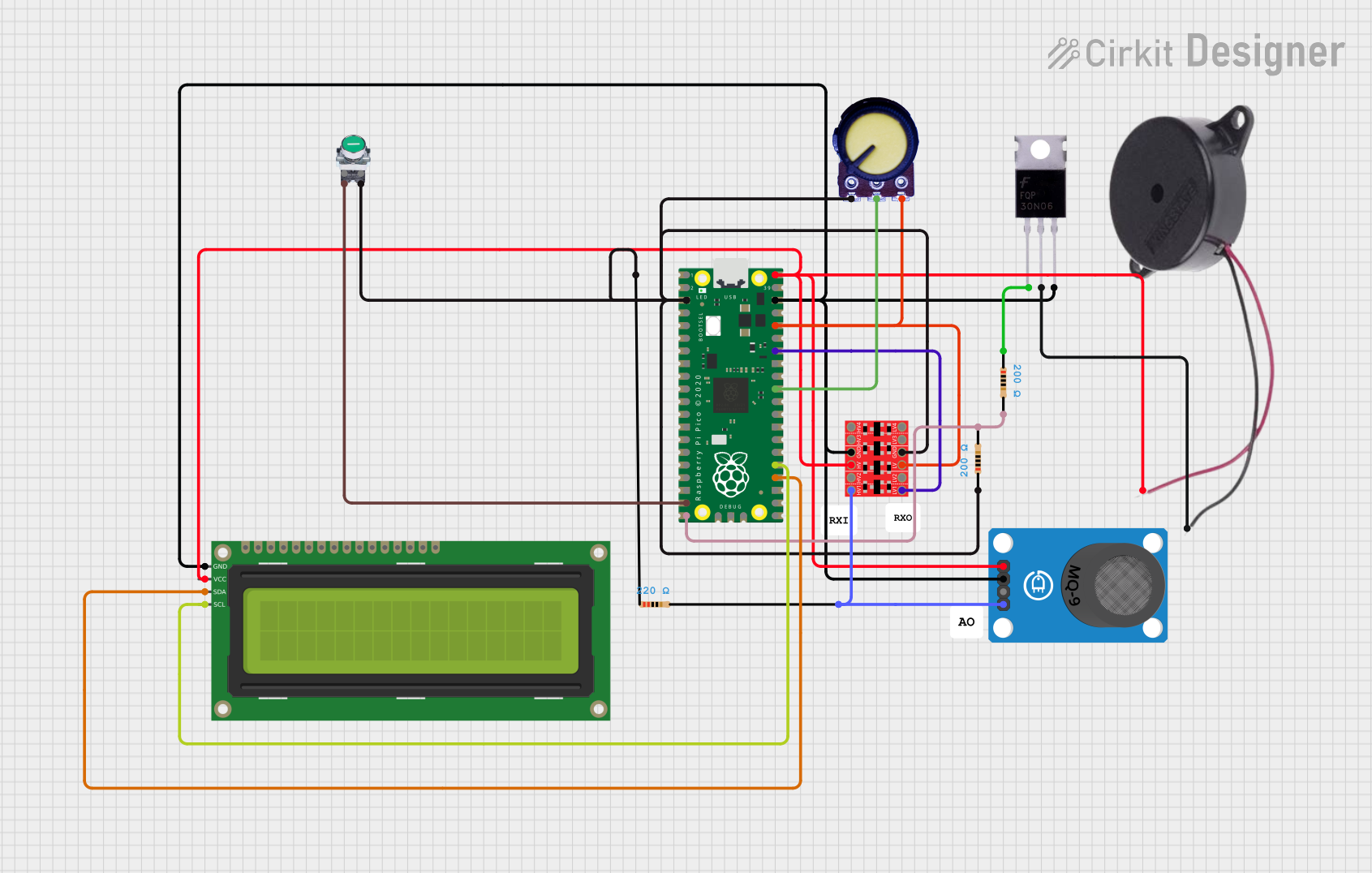
The Raspberry Pi Pico H Upside Down is a compact microcontroller board developed by Raspberry Pi, based on the RP2040 chip. This variant of the Pico H features pre-soldered headers and an upside-down pin orientation, making it ideal for applications where the board needs to be mounted in a specific orientation. It is designed for easy prototyping, embedded systems, and interfacing with a wide range of sensors and devices.
Explore Projects Built with Raspberry Pi Pico H Upside Down
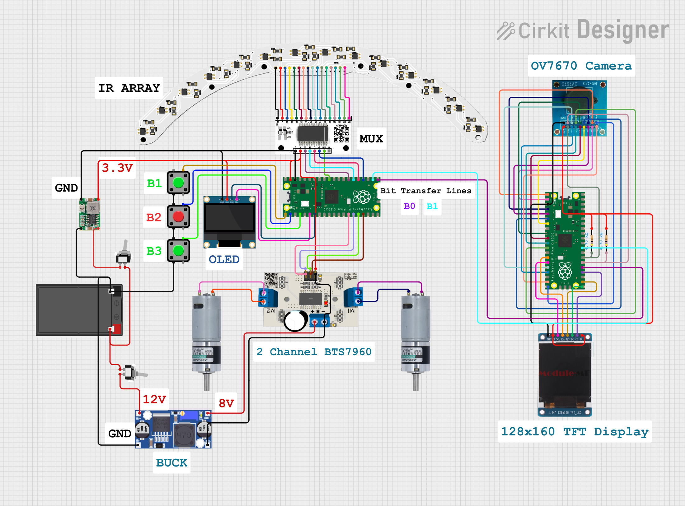
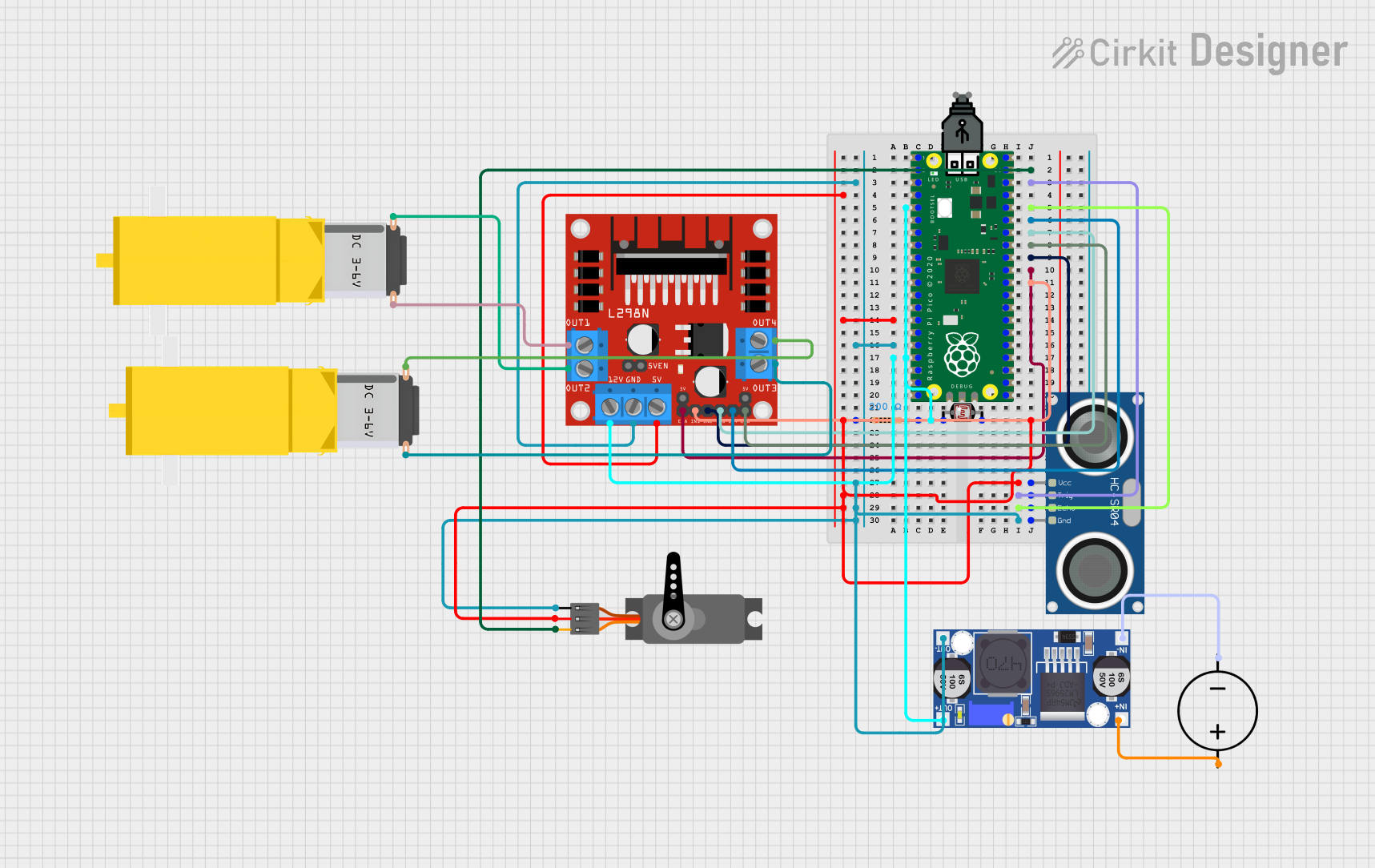
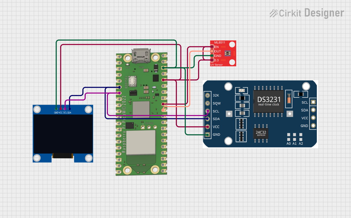
Explore Projects Built with Raspberry Pi Pico H Upside Down
Common Applications
- IoT (Internet of Things) devices
- Robotics and automation
- Sensor data acquisition
- Home automation systems
- Educational projects and prototyping
Technical Specifications
Key Technical Details
| Specification | Value |
|---|---|
| Microcontroller | RP2040 (Dual-core Arm Cortex-M0+ @ 133MHz) |
| Flash Memory | 2MB QSPI Flash |
| RAM | 264KB SRAM |
| GPIO Pins | 26 (3.3V logic level) |
| Communication Interfaces | I2C, SPI, UART |
| ADC Channels | 3 (12-bit resolution) |
| Operating Voltage | 3.3V |
| Input Voltage Range | 1.8V to 5.5V |
| USB Interface | Micro-USB (USB 1.1) |
| Dimensions | 51mm x 21mm |
Pin Configuration and Descriptions
The Raspberry Pi Pico H Upside Down has 40 pins, with pre-soldered headers. Below is the pinout description:
| Pin Number | Pin Name | Description |
|---|---|---|
| 1 | GP0 | General Purpose I/O, UART0 TX |
| 2 | GP1 | General Purpose I/O, UART0 RX |
| 3 | GND | Ground |
| 4 | GP2 | General Purpose I/O, I2C1 SDA |
| 5 | GP3 | General Purpose I/O, I2C1 SCL |
| ... | ... | ... (Refer to the official datasheet for |
| the full pinout) | ||
| 39 | 3V3_EN | Enable 3.3V regulator |
| 40 | VSYS | System input voltage |
For the complete pinout, refer to the official Raspberry Pi Pico documentation.
Usage Instructions
How to Use the Component in a Circuit
Powering the Board:
- The board can be powered via the Micro-USB port or through the VSYS pin (1.8V to 5.5V).
- Ensure the power supply is stable and within the specified range to avoid damage.
Connecting Peripherals:
- Use the GPIO pins to interface with sensors, actuators, or other devices.
- The pins operate at 3.3V logic levels. Use level shifters if interfacing with 5V devices.
Programming the Board:
- Connect the board to your computer via the Micro-USB cable.
- Hold the BOOTSEL button while plugging in the USB cable to enter USB mass storage mode.
- Drag and drop the firmware file (e.g., MicroPython or C/C++ binary) onto the board.
Example Circuit:
- Connect an LED to GP15 with a 330-ohm resistor in series.
- Use the following code to blink the LED.
Example Code for Arduino IDE
// This example code blinks an LED connected to GPIO 15 on the Raspberry Pi Pico H.
// Ensure the LED is connected with a current-limiting resistor (e.g., 330 ohms).

#define LED_PIN 15  // Define the GPIO pin for the LED

void setup() {
  pinMode(LED_PIN, OUTPUT);  // Set the LED pin as an output
}

void loop() {
  digitalWrite(LED_PIN, HIGH);  // Turn the LED on
  delay(500);                   // Wait for 500 milliseconds
  digitalWrite(LED_PIN, LOW);   // Turn the LED off
  delay(500);                   // Wait for 500 milliseconds
}
Important Considerations and Best Practices
- Voltage Levels: Ensure all connected devices operate at 3.3V logic levels or use level shifters.
- Pin Current Limits: Each GPIO pin can source/sink up to 12mA, with a total maximum of 50mA across all pins.
- Static Protection: Handle the board with care to avoid damage from electrostatic discharge (ESD).
Troubleshooting and FAQs
Common Issues and Solutions
The board is not recognized by the computer:
- Ensure the USB cable is data-capable (not just a charging cable).
- Hold the BOOTSEL button while connecting the board to enter USB mass storage mode.
GPIO pins are not working as expected:
- Verify the pin configuration in your code.
- Check for loose connections or incorrect wiring.
- Ensure the total current draw does not exceed the board's limits.
The board overheats:
- Check the input voltage on the VSYS pin. Ensure it is within the 1.8V to 5.5V range.
- Avoid short circuits on the GPIO pins.
Cannot upload code to the board:
- Ensure the correct firmware is being used (e.g., MicroPython or C/C++).
- Verify that the board is in USB mass storage mode when uploading firmware.
FAQs
Q: Can I use the Raspberry Pi Pico H Upside Down with 5V sensors?
A: The GPIO pins operate at 3.3V logic levels. Use a level shifter to safely interface with 5V sensors.
Q: What programming languages are supported?
A: The board supports C/C++, MicroPython, and CircuitPython.
Q: How do I reset the board to factory settings?
A: Re-flash the firmware by entering USB mass storage mode and uploading the desired firmware file.
Q: Can I power the board with batteries?
A: Yes, you can power the board via the VSYS pin using a battery pack within the 1.8V to 5.5V range.
For additional support, refer to the official Raspberry Pi Pico documentation or community forums.