
How to Use Heltec Lora 32 v2: Examples, Pinouts, and Specs
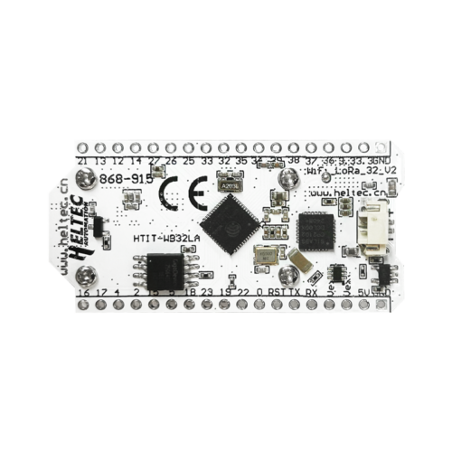
 Design with Heltec Lora 32 v2 in Cirkit Designer
Introduction
The Heltec LoRa 32 v2 is a compact development board designed by Heltec, featuring an ESP32 microcontroller with integrated LoRa (Long Range) communication capabilities. This board is ideal for Internet of Things (IoT) applications that require long-range wireless connectivity, low power consumption, and high processing power. It also includes an onboard OLED display for quick data visualization and debugging.
Explore Projects Built with Heltec Lora 32 v2
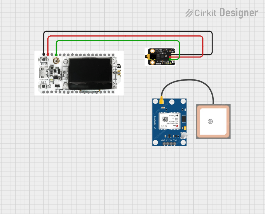 Open Project in Cirkit Designer
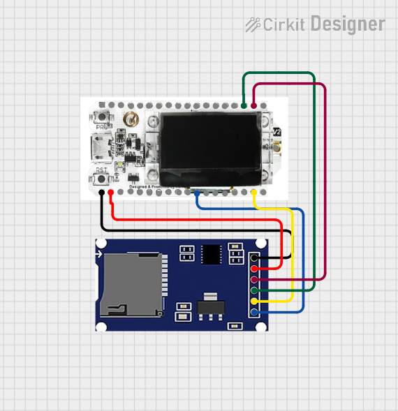 Open Project in Cirkit Designer
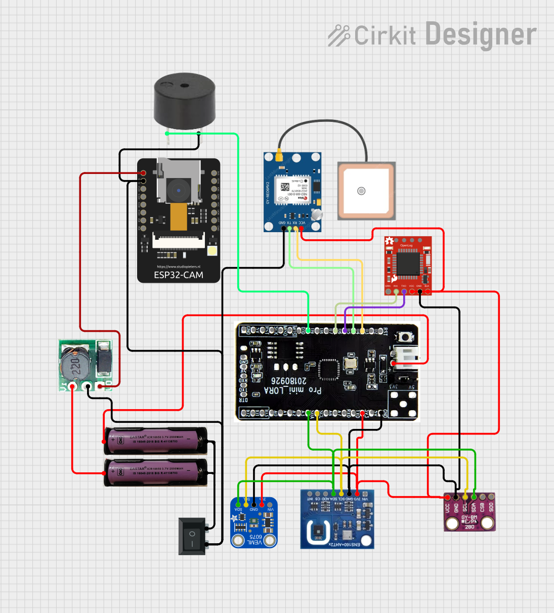 Open Project in Cirkit Designer
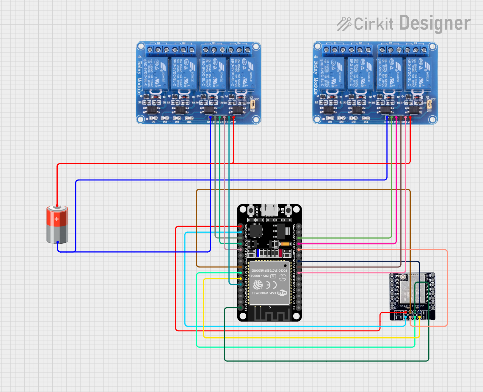 Open Project in Cirkit Designer
Explore Projects Built with Heltec Lora 32 v2
Open Project in Cirkit DesignerOpen Project in Cirkit DesignerOpen Project in Cirkit DesignerOpen Project in Cirkit DesignerCommon Applications and Use Cases
- IoT sensor networks
- Smart agriculture and environmental monitoring
- Asset tracking and geolocation
- Home automation systems
- Industrial monitoring and control
- Long-range wireless communication projects
Technical Specifications
Key Technical Details
| Parameter | Specification |
|---|---|
| Microcontroller | ESP32 (dual-core, 32-bit, Xtensa LX6) |
| LoRa Module | Semtech SX1276 |
| Frequency Band | 433 MHz / 868 MHz / 915 MHz (region-specific) |
| Flash Memory | 8 MB |
| SRAM | 520 KB |
| Operating Voltage | 3.3V |
| Input Voltage Range | 5V (via USB) or 3.7V (via LiPo battery) |
| Communication Interfaces | UART, SPI, I2C, GPIO, ADC, DAC |
| OLED Display | 0.96-inch, 128x64 pixels, monochrome |
| Antenna Connector | IPEX (external antenna required for LoRa communication) |
| Power Consumption | Ultra-low power consumption in deep sleep mode (as low as 10 µA) |
| Dimensions | 41 x 25 x 12 mm |
Pin Configuration and Descriptions
| Pin Name | Pin Number | Description |
|---|---|---|
| GND | Multiple | Ground connection |
| 3V3 | Multiple | 3.3V power output |
| VIN | - | Power input (5V via USB or 3.7V via LiPo battery) |
| GPIO0 | 0 | General-purpose I/O, also used for boot mode selection |
| GPIO21 | 21 | I2C SDA (data line) |
| GPIO22 | 22 | I2C SCL (clock line) |
| GPIO16 | 16 | LoRa reset pin |
| GPIO17 | 17 | LoRa DIO1 pin |
| GPIO18 | 18 | SPI SCK (clock line) |
| GPIO19 | 19 | SPI MISO (data input) |
| GPIO23 | 23 | SPI MOSI (data output) |
| GPIO25 | 25 | DAC1 (digital-to-analog converter output) |
| GPIO26 | 26 | DAC2 (digital-to-analog converter output) |
| GPIO32 | 32 | ADC1 (analog-to-digital converter input) |
| RST | - | Reset pin |
Usage Instructions
How to Use the Component in a Circuit
Powering the Board:
- Connect the board to a 5V USB power source or use a 3.7V LiPo battery via the JST connector.
- Ensure the power source is stable to avoid damaging the board.
Connecting the Antenna:
- Attach an external antenna to the IPEX connector for LoRa communication.
- Operating the LoRa module without an antenna may damage the hardware.
Programming the Board:
- Use the Arduino IDE or PlatformIO to program the Heltec LoRa 32 v2.
- Install the necessary board definitions and libraries (e.g., Heltec ESP32 and LoRa libraries).
Using the OLED Display:
- The onboard OLED display is connected via I2C (SDA: GPIO21, SCL: GPIO22).
- Use libraries like
U8g2orAdafruit_SSD1306to control the display.
LoRa Communication:
- Use the
LoRalibrary to send and receive data over long distances. - Configure the frequency band (433 MHz, 868 MHz, or 915 MHz) based on your region.
- Use the
Important Considerations and Best Practices
- Deep Sleep Mode: Utilize the ESP32's deep sleep mode to minimize power consumption in battery-powered applications.
- Antenna Placement: Ensure the antenna is placed away from metal objects to avoid signal interference.
- Voltage Levels: Avoid applying voltages higher than 3.3V to GPIO pins to prevent damage.
- Firmware Updates: Regularly update the firmware and libraries to ensure compatibility and access to new features.
Example Code for Arduino UNO Integration
Below is an example of using the Heltec LoRa 32 v2 to send a simple LoRa message:
#include <LoRa.h> // Include the LoRa library

#define SS 18    // LoRa module's SPI chip select pin
#define RST 14   // LoRa module's reset pin
#define DIO0 26  // LoRa module's DIO0 pin

void setup() {
  Serial.begin(9600); // Initialize serial communication
  while (!Serial);

  Serial.println("Initializing LoRa...");

  // Initialize LoRa module
  LoRa.setPins(SS, RST, DIO0);
  if (!LoRa.begin(915E6)) { // Set frequency to 915 MHz
    Serial.println("LoRa initialization failed!");
    while (1);
  }

  Serial.println("LoRa initialized successfully!");
}

void loop() {
  Serial.println("Sending message...");
  LoRa.beginPacket(); // Start a new LoRa packet
  LoRa.print("Hello, LoRa!"); // Add message to the packet
  LoRa.endPacket(); // Send the packet

  delay(5000); // Wait 5 seconds before sending the next message
}
Note: Replace 915E6 with the appropriate frequency for your region (e.g., 868E6 for Europe or 433E6 for some regions in Asia).
Troubleshooting and FAQs
Common Issues and Solutions
LoRa Module Not Initializing:
- Ensure the antenna is properly connected.
- Verify the frequency band is correctly set in the code.
- Check the wiring of the SPI pins (SS, RST, DIO0).
OLED Display Not Working:
- Confirm the I2C connections (SDA: GPIO21, SCL: GPIO22).
- Ensure the correct I2C address is used in the code (default:
0x3C). - Check for loose connections or damaged components.
Board Not Detected by Computer:
- Install the correct USB-to-serial driver (e.g., CP2102 or CH340).
- Try a different USB cable or port.
Low Signal Strength in LoRa Communication:
- Ensure the antenna is securely connected and positioned correctly.
- Avoid obstructions and interference from other devices.
FAQs
Q: Can I power the board with a 5V power supply directly?
A: Yes, you can power the board via the USB port or the VIN pin with a 5V supply.Q: What is the maximum range of LoRa communication?
A: The range depends on environmental factors but can reach up to 10 km in open areas.Q: Can I use the Heltec LoRa 32 v2 with other LoRa devices?
A: Yes, as long as the frequency band and communication settings match.Q: How do I update the firmware?
A: Use the Arduino IDE or PlatformIO to upload new firmware via the USB connection.
By following this documentation, you can effectively utilize the Heltec LoRa 32 v2 for your IoT and long-range communication projects.