How to Use 2N3906: Examples, Pinouts, and Specs
Introduction
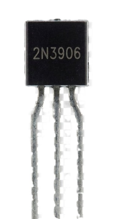
The 2N3906 is a general-purpose PNP bipolar junction transistor (BJT) manufactured by ONSEMI. It is widely used in low-power amplification and switching applications. With a maximum collector current of 200 mA and a maximum collector-emitter voltage of 40 V, the 2N3906 is a versatile component suitable for a variety of electronic circuits. Its compact TO-92 package makes it ideal for use in space-constrained designs.
Explore Projects Built with 2N3906

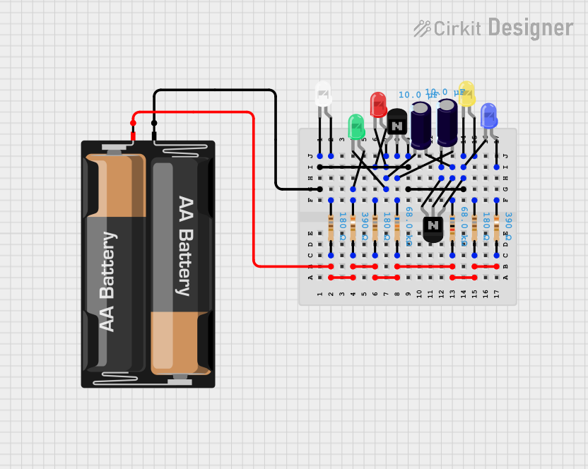
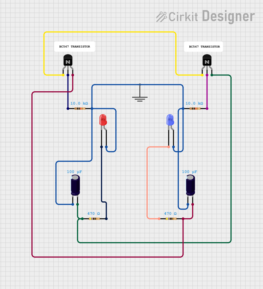
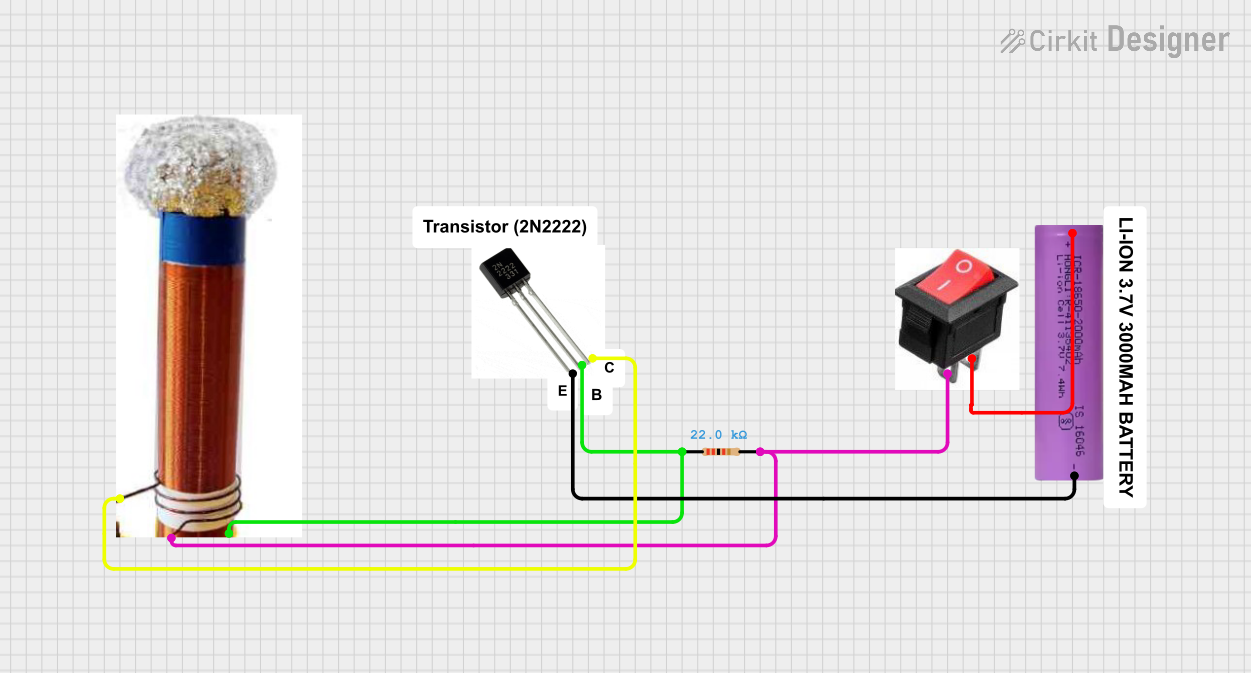
Explore Projects Built with 2N3906
Common Applications
- Signal amplification in low-power circuits
- Switching small loads in electronic devices
- Oscillator and timer circuits
- General-purpose analog and digital circuits
Technical Specifications
Key Specifications
| Parameter | Value |
|---|---|
| Manufacturer | ONSEMI |
| Part Number | 2N3906 |
| Transistor Type | PNP |
| Maximum Collector-Emitter Voltage (VCEO) | 40 V |
| Maximum Collector-Base Voltage (VCBO) | 40 V |
| Maximum Emitter-Base Voltage (VEBO) | 5 V |
| Maximum Collector Current (IC) | 200 mA |
| Maximum Power Dissipation (PD) | 625 mW |
| DC Current Gain (hFE) | 100 to 300 |
| Transition Frequency (fT) | 250 MHz |
| Package Type | TO-92 |
| Operating Temperature Range | -55°C to +150°C |
Pin Configuration
The 2N3906 is housed in a TO-92 package with three pins. The pinout is as follows:
| Pin Number | Pin Name | Description |
|---|---|---|
| 1 | Emitter | Current flows out of this pin. |
| 2 | Base | Controls the transistor's operation. |
| 3 | Collector | Current flows into this pin. |
Below is a diagram of the TO-92 package for reference:
   _______
  |       |
  |       |
  |_______|
   | | |
   1 2 3
   E B C
Usage Instructions
Using the 2N3906 in a Circuit
The 2N3906 operates as a PNP transistor, meaning it conducts current when the base is at a lower voltage than the emitter. It can be used in two primary modes:
- Switching Mode: The transistor acts as an electronic switch, turning on or off a connected load.
- Amplification Mode: The transistor amplifies small input signals applied to the base.
Example Circuit: LED Control
The following example demonstrates how to use the 2N3906 to control an LED:
Circuit Description:
- The emitter is connected to the positive voltage supply (VCC).
- The collector is connected to the LED and a current-limiting resistor.
- The base is connected to a control signal through a base resistor.
Arduino Code Example: If you are using an Arduino UNO to control the 2N3906, the following code can be used:
// Define the pin connected to the base of the 2N3906
const int basePin = 9;

void setup() {
  // Set the base pin as an output
  pinMode(basePin, OUTPUT);
}

void loop() {
  // Turn the LED on by setting the base low
  digitalWrite(basePin, LOW);
  delay(1000); // Wait for 1 second

  // Turn the LED off by setting the base high
  digitalWrite(basePin, HIGH);
  delay(1000); // Wait for 1 second
}
Important Considerations
- Base Resistor: Always use a resistor between the base and the control signal to limit the base current. A typical value is 1 kΩ.
- Power Dissipation: Ensure the total power dissipation does not exceed 625 mW.
- Polarity: Double-check the polarity of the connections, as reversing the emitter and collector can damage the transistor.
- Voltage Ratings: Do not exceed the maximum voltage ratings for VCEO, VCBO, or VEBO.
Troubleshooting and FAQs
Common Issues
Transistor Not Switching:
- Cause: Insufficient base current or incorrect base resistor value.
- Solution: Verify the base resistor value and ensure the base current is sufficient to saturate the transistor.
Overheating:
- Cause: Exceeding the maximum power dissipation or collector current.
- Solution: Check the load current and ensure it is within the 200 mA limit. Use a heatsink if necessary.
No Output Signal:
- Cause: Incorrect pin connections or damaged transistor.
- Solution: Verify the pinout and ensure the emitter, base, and collector are connected correctly.
FAQs
Q1: Can the 2N3906 be used for high-frequency applications?
A1: Yes, the 2N3906 has a transition frequency (fT) of 250 MHz, making it suitable for high-frequency applications.
Q2: What is the difference between the 2N3906 and 2N3904?
A2: The 2N3906 is a PNP transistor, while the 2N3904 is an NPN transistor. They are complementary components and can be used together in push-pull amplifier circuits.
Q3: Can I use the 2N3906 to drive a motor?
A3: The 2N3906 is not suitable for driving high-power motors due to its 200 mA maximum collector current. For motor control, consider using a power transistor or MOSFET.
By following this documentation, you can effectively use the 2N3906 in your electronic projects.