Cirkit Designer Logo
Cirkit Designer
Your all-in-one circuit design IDE
Home / 
Component Documentation

How to Use MH-MINI-360 Buck Converter: Examples, Pinouts, and Specs

Image of MH-MINI-360 Buck Converter
Cirkit Designer LogoDesign with MH-MINI-360 Buck Converter in Cirkit Designer

Introduction

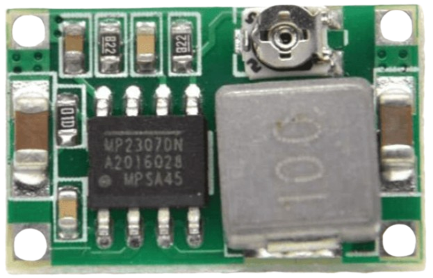
The MH-MINI-360 is a compact and highly efficient DC-DC buck converter designed to step down higher input voltages to lower, stable output voltages. Its small size and high efficiency make it ideal for powering low-voltage devices from higher voltage sources, such as batteries or power supplies. This module is widely used in DIY electronics, embedded systems, and portable devices where space and power efficiency are critical.

Explore Projects Built with MH-MINI-360 Buck Converter

Use Cirkit Designer to design, explore, and prototype these projects online. Some projects support real-time simulation. Click "Open Project" to start designing instantly!
Dual Motor Control Circuit with Directional Switching and Voltage Regulation
Image of Pencuci Kipas: A project utilizing MH-MINI-360 Buck Converter in a practical application
This circuit features a 12V battery connected through a rocker switch to two buck converters, one of which steps down the voltage to power two DC mini metal gear motors, and the other is connected to a directional switch that controls a third DC mini metal gear motor. The XL4015 5A DC Buck Step-down converter's output is connected to two motors, allowing them to run at a reduced voltage, while the other buck converter's output is routed through a directional switch to control the direction of the third motor.
Cirkit Designer LogoOpen Project in Cirkit Designer
Battery-Powered ESP32 Devkit V1 with Buck Converter and Switch Control
Image of Autonomus Car: A project utilizing MH-MINI-360 Buck Converter in a practical application
This circuit is a power management system that uses two 18650 Li-ion batteries to supply power through a toggle switch and a rocker switch to an LM2956 Buck Converter. The buck converter steps down the voltage to a suitable level for a connected device via a Micro USB cable.
Cirkit Designer LogoOpen Project in Cirkit Designer
Arduino UNO Wi-Fi Controlled DC Motor Driver with Battery Management System
Image of RC Ball: A project utilizing MH-MINI-360 Buck Converter in a practical application
This circuit is a motor control system powered by a 3s 20A BMS and 18650 Li-ion batteries, which drives two DC Mini Metal Gear Motors using an L298N motor driver. The Arduino UNO R4 WiFi microcontroller is used to control the motor driver, and a buck converter provides regulated power to a Type-C port.
Cirkit Designer LogoOpen Project in Cirkit Designer
CNC Machine Control System with Dual tb6600 Stepper Drivers and MAch3 USB Interface
Image of Jayshree CNC: A project utilizing MH-MINI-360 Buck Converter in a practical application
This circuit appears to be a control system for a CNC machine or similar automated equipment. It includes two tb6600 Micro Stepping Motor Drivers for controlling stepper motors, a DC power source with a step-down buck converter to provide the necessary voltage levels, and a 4-channel relay module for switching higher power loads. The MAch3 CNC USB interface suggests the system is designed to interface with computer numerical control software, and the RMCS_3001 BLDC Driver indicates the presence of a brushless DC motor control. The Tiva C launchpad microcontroller and various connectors imply that the system is modular and may be programmable for specific automation tasks.
Cirkit Designer LogoOpen Project in Cirkit Designer

Explore Projects Built with MH-MINI-360 Buck Converter

Use Cirkit Designer to design, explore, and prototype these projects online. Some projects support real-time simulation. Click "Open Project" to start designing instantly!
Image of Pencuci Kipas: A project utilizing MH-MINI-360 Buck Converter in a practical application
Dual Motor Control Circuit with Directional Switching and Voltage Regulation
This circuit features a 12V battery connected through a rocker switch to two buck converters, one of which steps down the voltage to power two DC mini metal gear motors, and the other is connected to a directional switch that controls a third DC mini metal gear motor. The XL4015 5A DC Buck Step-down converter's output is connected to two motors, allowing them to run at a reduced voltage, while the other buck converter's output is routed through a directional switch to control the direction of the third motor.
Cirkit Designer LogoOpen Project in Cirkit Designer
Image of Autonomus Car: A project utilizing MH-MINI-360 Buck Converter in a practical application
Battery-Powered ESP32 Devkit V1 with Buck Converter and Switch Control
This circuit is a power management system that uses two 18650 Li-ion batteries to supply power through a toggle switch and a rocker switch to an LM2956 Buck Converter. The buck converter steps down the voltage to a suitable level for a connected device via a Micro USB cable.
Cirkit Designer LogoOpen Project in Cirkit Designer
Image of RC Ball: A project utilizing MH-MINI-360 Buck Converter in a practical application
Arduino UNO Wi-Fi Controlled DC Motor Driver with Battery Management System
This circuit is a motor control system powered by a 3s 20A BMS and 18650 Li-ion batteries, which drives two DC Mini Metal Gear Motors using an L298N motor driver. The Arduino UNO R4 WiFi microcontroller is used to control the motor driver, and a buck converter provides regulated power to a Type-C port.
Cirkit Designer LogoOpen Project in Cirkit Designer
Image of Jayshree CNC: A project utilizing MH-MINI-360 Buck Converter in a practical application
CNC Machine Control System with Dual tb6600 Stepper Drivers and MAch3 USB Interface
This circuit appears to be a control system for a CNC machine or similar automated equipment. It includes two tb6600 Micro Stepping Motor Drivers for controlling stepper motors, a DC power source with a step-down buck converter to provide the necessary voltage levels, and a 4-channel relay module for switching higher power loads. The MAch3 CNC USB interface suggests the system is designed to interface with computer numerical control software, and the RMCS_3001 BLDC Driver indicates the presence of a brushless DC motor control. The Tiva C launchpad microcontroller and various connectors imply that the system is modular and may be programmable for specific automation tasks.
Cirkit Designer LogoOpen Project in Cirkit Designer

Common Applications and Use Cases

  • Powering microcontrollers (e.g., Arduino, ESP32, Raspberry Pi Pico)
  • Battery-powered projects requiring voltage regulation
  • LED drivers and lighting systems
  • Portable electronics and wearables
  • Robotics and IoT devices

Technical Specifications

The MH-MINI-360 buck converter is designed to deliver reliable performance in a variety of applications. Below are its key technical details:

Parameter Specification
Input Voltage Range 4.75V to 23V
Output Voltage Range 1.0V to 17V (adjustable via potentiometer)
Maximum Output Current 3A (with proper heat dissipation)
Efficiency Up to 96%
Switching Frequency 340 kHz
Dimensions 17mm x 11mm x 3.8mm
Operating Temperature -40°C to +85°C

Pin Configuration and Descriptions

The MH-MINI-360 has four pins for input and output connections:

Pin Name Description
VIN Positive input voltage (4.75V to 23V)
GND Ground (common for input and output)
VOUT Positive output voltage (adjustable)
GND Ground (common for input and output)

Usage Instructions

How to Use the MH-MINI-360 in a Circuit

  1. Connect Input Voltage:

    • Connect the VIN pin to the positive terminal of your power source (e.g., battery or power supply).
    • Connect the GND pin to the ground terminal of your power source.
  2. Connect Output Voltage:

    • Connect the VOUT pin to the positive terminal of the load (e.g., microcontroller, LED, or other device).
    • Connect the GND pin to the ground terminal of the load.
  3. Adjust Output Voltage:

    • Use a small screwdriver to turn the onboard potentiometer clockwise to increase the output voltage or counterclockwise to decrease it.
    • Measure the output voltage with a multimeter to ensure it matches your desired value before connecting the load.
  4. Verify Connections:

    • Double-check all connections to ensure proper polarity and avoid short circuits.

Important Considerations and Best Practices

  • Heat Dissipation: The module can handle up to 3A, but proper heat dissipation (e.g., a heatsink or adequate airflow) is required for high-current applications.
  • Input Voltage: Ensure the input voltage is at least 1.5V higher than the desired output voltage for stable operation.
  • Output Voltage Adjustment: Always adjust the output voltage without a load connected to prevent damage to sensitive devices.
  • Capacitor Requirements: For optimal performance, ensure the input and output capacitors are in place (pre-soldered on the module).

Example: Using MH-MINI-360 with Arduino UNO

Below is an example of how to use the MH-MINI-360 to power an Arduino UNO from a 12V power source:

  1. Set the output voltage of the MH-MINI-360 to 5V using the potentiometer.
  2. Connect the VIN pin of the MH-MINI-360 to the 12V power source.
  3. Connect the VOUT pin of the MH-MINI-360 to the 5V pin of the Arduino UNO.
  4. Connect the GND pins of the MH-MINI-360, power source, and Arduino UNO together.
// Example code for Arduino UNO powered by MH-MINI-360
// This code blinks an LED connected to pin 13

void setup() {
  pinMode(13, OUTPUT); // Set pin 13 as an output
}

void loop() {
  digitalWrite(13, HIGH); // Turn the LED on
  delay(1000);            // Wait for 1 second
  digitalWrite(13, LOW);  // Turn the LED off
  delay(1000);            // Wait for 1 second
}

Troubleshooting and FAQs

Common Issues and Solutions

  1. No Output Voltage:

    • Cause: Incorrect wiring or insufficient input voltage.
    • Solution: Verify all connections and ensure the input voltage is within the specified range.
  2. Output Voltage Fluctuates:

    • Cause: Insufficient input power or unstable power source.
    • Solution: Use a stable power source and ensure proper input and output capacitors are in place.
  3. Overheating:

    • Cause: Excessive current draw or poor heat dissipation.
    • Solution: Reduce the load current or add a heatsink to the module.
  4. Cannot Adjust Output Voltage:

    • Cause: Faulty potentiometer or incorrect adjustment.
    • Solution: Check the potentiometer for damage and adjust it carefully with a screwdriver.

FAQs

Q1: Can the MH-MINI-360 be used to power a Raspberry Pi?
A1: Yes, but ensure the output voltage is set to 5V and the current requirement of the Raspberry Pi (typically 2.5A for most models) does not exceed the module's capacity.

Q2: Is the module protected against reverse polarity?
A2: No, the MH-MINI-360 does not have reverse polarity protection. Always double-check your connections to avoid damage.

Q3: Can I use the MH-MINI-360 to charge a battery?
A3: While it can regulate voltage, it is not designed as a dedicated battery charger. Use a proper charging module for battery applications.

Q4: What is the efficiency of the module at low loads?
A4: The efficiency remains high (typically above 80%) even at low loads, but it is most efficient at moderate to high loads.