How to Use Tower Light with Buzzer T50: Examples, Pinouts, and Specs
Introduction
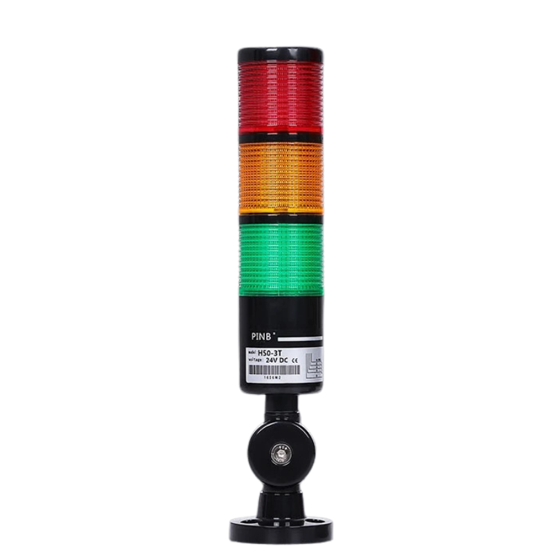
The Tower Light with Buzzer T50 is a versatile signaling device that combines a multi-tiered tower light for visual alerts and a buzzer for audible notifications. This component is widely used in industrial and automation environments to indicate machine status, alarms, or process conditions. Its compact design and robust construction make it suitable for a variety of applications, including factory automation, safety systems, and equipment monitoring.
Explore Projects Built with Tower Light with Buzzer T50
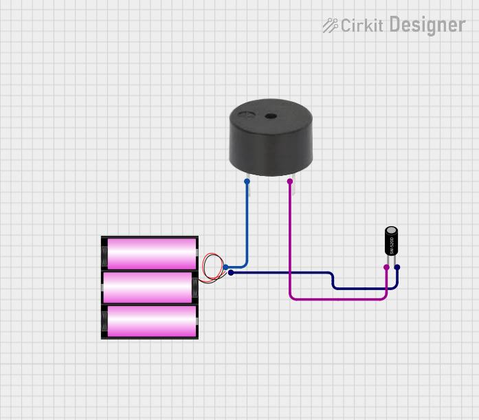
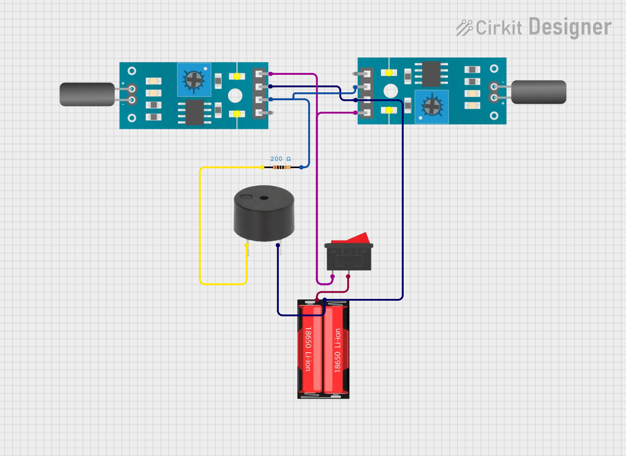
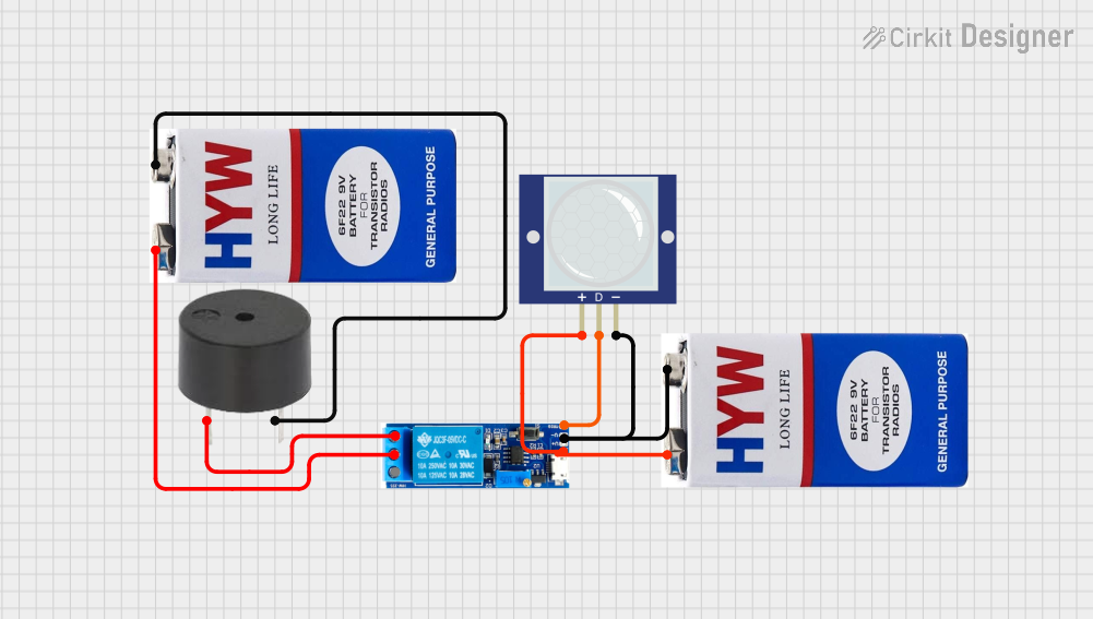
Explore Projects Built with Tower Light with Buzzer T50
Common Applications
- Indicating machine status (e.g., idle, running, error)
- Alerting operators to process alarms or warnings
- Enhancing safety in industrial environments
- Providing visual and audible feedback in automated systems
Technical Specifications
The Tower Light with Buzzer T50 is designed to operate reliably in demanding environments. Below are its key technical details:
| Parameter | Specification |
|---|---|
| Operating Voltage | 12V DC / 24V DC / 110V AC / 220V AC |
| Current Consumption | 50-200 mA (varies by model) |
| Light Colors | Red, Yellow, Green (3-tier standard) |
| Buzzer Sound Level | 85-95 dB at 1 meter |
| Buzzer Frequency | 2-4 kHz |
| Mounting Style | Pole or direct mount |
| Operating Temperature | -10°C to 50°C |
| Protection Rating | IP54 (dust and splash resistant) |
Pin Configuration and Descriptions
The Tower Light with Buzzer T50 typically has a multi-wire connection for controlling the lights and buzzer. Below is the pin configuration:
| Wire Color | Function |
|---|---|
| Red | Power supply for Red light |
| Yellow | Power supply for Yellow light |
| Green | Power supply for Green light |
| Black | Common ground (GND) |
| White | Power supply for Buzzer |
Usage Instructions
How to Use the Component in a Circuit
- Power Supply: Ensure the operating voltage matches the model of the Tower Light with Buzzer T50 (e.g., 12V DC, 24V DC, or AC versions). Use a regulated power supply to avoid damage.
- Wiring: Connect the wires as per the pin configuration table:
- Connect the Black wire to the ground (GND) of the power supply.
- Connect the Red, Yellow, and Green wires to the respective control signals or switches for the lights.
- Connect the White wire to the control signal for the buzzer.
- Control Signals: Use switches, relays, or microcontroller GPIO pins to control the lights and buzzer. Ensure the control signals are compatible with the operating voltage.
Important Considerations and Best Practices
- Current Limiting: If using a microcontroller (e.g., Arduino UNO), use transistors or relays to handle the current required by the lights and buzzer.
- Polarity: Double-check the polarity of the connections to avoid damage to the component.
- Environment: Install the device in a location that is within its operating temperature range and protected from excessive dust or water.
- Testing: Test each light and the buzzer individually before integrating into a larger system.
Example: Connecting to an Arduino UNO
Below is an example of how to connect and control the Tower Light with Buzzer T50 using an Arduino UNO:
Circuit Diagram
- Connect the Black wire to the Arduino GND.
- Connect the Red, Yellow, and Green wires to Arduino digital pins 8, 9, and 10, respectively, through NPN transistors.
- Connect the White wire to Arduino digital pin 11 through an NPN transistor.
Arduino Code
// Pin definitions for Tower Light with Buzzer T50
const int redLightPin = 8;    // Red light control pin
const int yellowLightPin = 9; // Yellow light control pin
const int greenLightPin = 10; // Green light control pin
const int buzzerPin = 11;     // Buzzer control pin

void setup() {
  // Set pins as outputs
  pinMode(redLightPin, OUTPUT);
  pinMode(yellowLightPin, OUTPUT);
  pinMode(greenLightPin, OUTPUT);
  pinMode(buzzerPin, OUTPUT);
}

void loop() {
  // Example sequence: Red light and buzzer on
  digitalWrite(redLightPin, HIGH);
  digitalWrite(buzzerPin, HIGH);
  delay(1000); // Wait for 1 second

  // Yellow light on, others off
  digitalWrite(redLightPin, LOW);
  digitalWrite(yellowLightPin, HIGH);
  digitalWrite(buzzerPin, LOW);
  delay(1000); // Wait for 1 second

  // Green light on, others off
  digitalWrite(yellowLightPin, LOW);
  digitalWrite(greenLightPin, HIGH);
  delay(1000); // Wait for 1 second

  // Turn all lights and buzzer off
  digitalWrite(greenLightPin, LOW);
  digitalWrite(buzzerPin, LOW);
  delay(1000); // Wait for 1 second
}
Troubleshooting and FAQs
Common Issues and Solutions
Lights or Buzzer Not Working:
- Cause: Incorrect wiring or insufficient power supply.
- Solution: Verify the wiring connections and ensure the power supply matches the operating voltage.
Buzzer Too Quiet:
- Cause: Insufficient current or incorrect control signal.
- Solution: Check the control signal and ensure it provides adequate current.
Intermittent Operation:
- Cause: Loose connections or unstable power supply.
- Solution: Secure all connections and use a regulated power supply.
Overheating:
- Cause: Operating outside the specified voltage or temperature range.
- Solution: Ensure the component is used within its rated specifications.
FAQs
Q: Can I use the Tower Light with Buzzer T50 outdoors?
A: The T50 has an IP54 rating, which provides limited protection against dust and splashes. For outdoor use, additional weatherproofing is recommended.
Q: Can I control the lights and buzzer independently?
A: Yes, each light and the buzzer have separate control wires, allowing independent operation.
Q: What is the maximum distance for wiring?
A: The maximum wiring distance depends on the wire gauge and power supply. For long distances, use thicker wires to minimize voltage drop.
Q: Can I use this component with a 5V microcontroller?
A: Yes, but you will need transistors or relays to interface the 5V control signals with the higher operating voltage of the T50.