How to Use 1.28" LCD Display: Examples, Pinouts, and Specs
Introduction
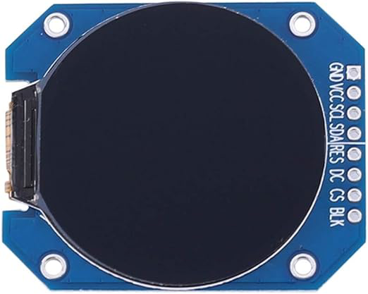
The 1.28" LCD Display by Dongker is a compact liquid crystal display designed for visual output in electronic devices. With its small form factor, this display is ideal for projects requiring a lightweight and space-efficient solution. It is commonly used in applications such as wearable devices, IoT projects, handheld instruments, and other compact electronic systems. The display provides clear and vibrant visuals, making it suitable for both text and graphical content.
Explore Projects Built with 1.28" LCD Display


Explore Projects Built with 1.28" LCD Display
Technical Specifications
Below are the key technical details of the 1.28" LCD Display:
| Specification | Details |
|---|---|
| Manufacturer | Dongker |
| Display Type | LCD |
| Screen Size | 1.28 inches |
| Resolution | 240 x 240 pixels |
| Interface | SPI (Serial Peripheral Interface) |
| Operating Voltage | 3.3V |
| Operating Current | ~20mA |
| Backlight | LED |
| Viewing Angle | Wide |
| Dimensions | 36mm x 36mm x 4mm |
| Operating Temperature | -20°C to 70°C |
Pin Configuration and Descriptions
The 1.28" LCD Display typically comes with an 8-pin interface. Below is the pinout and description:
| Pin | Name | Description |
|---|---|---|
| 1 | GND | Ground connection |
| 2 | VCC | Power supply (3.3V) |
| 3 | SCL | Serial Clock Line for SPI communication |
| 4 | SDA | Serial Data Line for SPI communication |
| 5 | RES | Reset pin (active low) |
| 6 | DC | Data/Command control pin (High for data, Low for command) |
| 7 | CS | Chip Select (active low) |
| 8 | BLK | Backlight control (connect to GND to turn off or leave unconnected for always on) |
Usage Instructions
How to Use the Component in a Circuit
- Power Supply: Connect the
VCCpin to a 3.3V power source and theGNDpin to ground. - SPI Communication: Use the
SCLandSDApins to establish SPI communication with a microcontroller. - Control Pins:
- Connect the
RESpin to a GPIO pin on the microcontroller for resetting the display. - Use the
DCpin to differentiate between data and command signals. - The
CSpin should be connected to a GPIO pin to enable or disable the display.
- Connect the
- Backlight: The
BLKpin can be left unconnected for the backlight to remain on or connected to GND to turn it off.
Important Considerations and Best Practices
- Voltage Levels: Ensure the display operates at 3.3V. If using a 5V microcontroller, use a level shifter to avoid damage.
- SPI Speed: Configure the SPI clock speed according to the display's datasheet to ensure reliable communication.
- Initialization: Always initialize the display using the appropriate commands before sending data.
- Backlight Control: For power-saving applications, consider controlling the backlight using a transistor or PWM signal.
Example Code for Arduino UNO
Below is an example of how to use the 1.28" LCD Display with an Arduino UNO. This example uses the Adafruit_GFX and Adafruit_ST7789 libraries (assuming the display uses the ST7789 driver).
#include <Adafruit_GFX.h>      // Core graphics library
#include <Adafruit_ST7789.h>   // ST7789 driver library
#include <SPI.h>               // SPI library

// Define pin connections
#define TFT_CS    10  // Chip Select pin
#define TFT_RST   9   // Reset pin
#define TFT_DC    8   // Data/Command pin

// Initialize the display object
Adafruit_ST7789 tft = Adafruit_ST7789(TFT_CS, TFT_DC, TFT_RST);

void setup() {
  // Initialize serial communication for debugging
  Serial.begin(9600);
  Serial.println("1.28\" LCD Display Test");

  // Initialize the display
  tft.init(240, 240);  // Initialize with 240x240 resolution
  tft.setRotation(0);  // Set display orientation

  // Fill the screen with a color
  tft.fillScreen(ST77XX_BLACK);

  // Display some text
  tft.setTextColor(ST77XX_WHITE);
  tft.setTextSize(2);
  tft.setCursor(10, 10);
  tft.println("Hello, World!");
}

void loop() {
  // Add any additional functionality here
}
Notes:
- Install the
Adafruit_GFXandAdafruit_ST7789libraries via the Arduino Library Manager before running the code. - Adjust the pin definitions (
TFT_CS,TFT_RST,TFT_DC) to match your wiring.
Troubleshooting and FAQs
Common Issues and Solutions
Display Not Turning On:
- Verify the power supply connections (
VCCandGND). - Ensure the backlight pin (
BLK) is not connected to GND if you want the backlight on.
- Verify the power supply connections (
No Output on the Screen:
- Check the SPI connections (
SCL,SDA,CS,DC). - Ensure the display is properly initialized in the code.
- Check the SPI connections (
Flickering or Unstable Display:
- Reduce the SPI clock speed in the microcontroller settings.
- Check for loose or poor-quality connections.
Incorrect Colors or Graphics:
- Verify the initialization sequence in the code matches the display driver (e.g., ST7789).
- Ensure the
setRotation()function is used correctly for the desired orientation.
FAQs
Q: Can I use this display with a 5V microcontroller?
A: Yes, but you must use a level shifter to convert the 5V logic signals to 3.3V to avoid damaging the display.
Q: How do I control the backlight brightness?
A: You can use a PWM signal on the BLK pin to adjust the brightness.
Q: What is the maximum SPI clock speed supported?
A: Refer to the display's datasheet for the maximum SPI clock speed, typically up to 15-20 MHz.
Q: Can this display show images?
A: Yes, you can display images by converting them to a compatible format (e.g., BMP) and using the appropriate library functions.
By following this documentation, you can effectively integrate the Dongker 1.28" LCD Display into your projects and troubleshoot common issues.