How to Use NE555 Pulse Frequency Duty Cycle Adjustable Module Square Wave Signal Generator: Examples, Pinouts, and Specs
Introduction
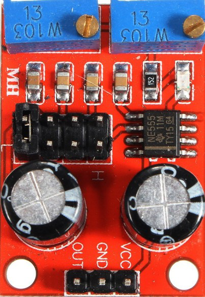
The NE555 Pulse Frequency Duty Cycle Adjustable Module is a versatile electronic component based on the NE555 timer IC. It is designed to generate precise timing and oscillation signals, with adjustable pulse frequency and duty cycle. This module is widely used in applications such as signal generation, timing delays, and waveform generation. Its ease of use and flexibility make it a popular choice for hobbyists, students, and professionals alike.
Explore Projects Built with NE555 Pulse Frequency Duty Cycle Adjustable Module Square Wave Signal Generator

Explore Projects Built with NE555 Pulse Frequency Duty Cycle Adjustable Module Square Wave Signal Generator
Common Applications and Use Cases
- Generating square wave signals for testing and debugging circuits
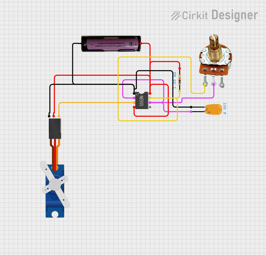
- Adjustable pulse-width modulation (PWM) for motor speed control
- Timing delays in electronic circuits
- Frequency generation for audio and RF applications
- LED dimming and brightness control
- Clock signal generation for digital circuits
Technical Specifications
Below are the key technical details of the NE555 Pulse Frequency Duty Cycle Adjustable Module:
| Parameter | Specification |
|---|---|
| Operating Voltage | 5V to 15V DC |
| Output Voltage | Approximately equal to input voltage |
| Output Current | Up to 200mA |
| Frequency Range | ~1Hz to 200kHz (adjustable) |
| Duty Cycle Range | ~10% to 90% (adjustable) |
| Output Waveform | Square wave |
| Dimensions | ~32mm x 22mm x 10mm |
Pin Configuration and Descriptions
The module typically has a 4-pin interface for easy integration into circuits. Below is the pinout:
| Pin | Name | Description |
|---|---|---|
| 1 | VCC | Connect to the positive supply voltage (5V to 15V DC). |
| 2 | GND | Connect to the ground of the power supply. |
| 3 | OUT | Square wave output signal. Connect this pin to the load or circuit input. |
| 4 | ADJ | Adjustment pin for frequency and duty cycle. Use the onboard potentiometers. |
Usage Instructions
How to Use the Component in a Circuit
- Power the Module: Connect the
VCCpin to a DC power supply (5V to 15V) and theGNDpin to the ground. - Adjust Frequency and Duty Cycle: Use the two onboard potentiometers:
- One potentiometer adjusts the frequency of the square wave.
- The other potentiometer adjusts the duty cycle (the ratio of ON time to OFF time).
- Connect the Output: The
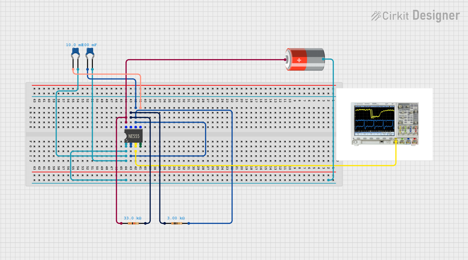
OUTpin provides the square wave signal. Connect this pin to the input of the circuit or device you want to control or test. - Test the Signal: Use an oscilloscope or multimeter to verify the output waveform and adjust the potentiometers as needed.
Important Considerations and Best Practices
- Power Supply: Ensure the power supply voltage is within the module's operating range (5V to 15V). Exceeding this range may damage the module.
- Load Current: The output pin can drive loads up to 200mA. For higher loads, use an external transistor or MOSFET.
- Signal Stability: For precise applications, use a stable power supply to minimize noise and fluctuations in the output signal.
- Potentiometer Adjustment: Turn the potentiometers slowly to avoid overshooting the desired frequency or duty cycle.
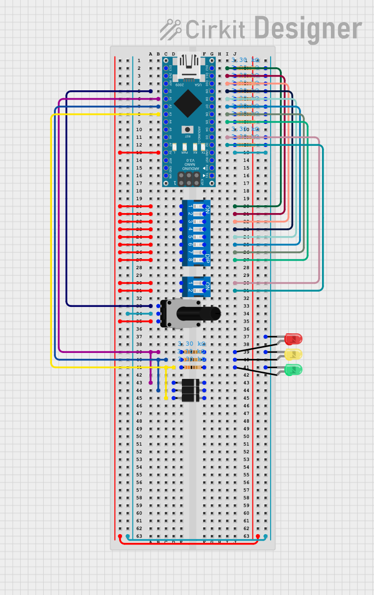
Example: Using the Module with an Arduino UNO
The NE555 module can be used to generate a square wave signal for an Arduino UNO. Below is an example of how to read the signal using the Arduino's digital input pin:
// Example: Reading the NE555 square wave signal with Arduino UNO
// Connect the NE555 OUT pin to Arduino digital pin 2
// Connect NE555 VCC and GND to Arduino 5V and GND, respectively

const int signalPin = 2; // Pin connected to NE555 OUT
int signalState = 0;     // Variable to store the signal state

void setup() {
  pinMode(signalPin, INPUT); // Set the signal pin as input
  Serial.begin(9600);       // Initialize serial communication
}

void loop() {
  signalState = digitalRead(signalPin); // Read the signal state
  Serial.print("Signal State: ");
  Serial.println(signalState);         // Print the signal state to the Serial Monitor
  delay(100);                          // Small delay for readability
}
Troubleshooting and FAQs
Common Issues and Solutions
No Output Signal
- Cause: Incorrect power supply connection.
- Solution: Verify that the
VCCandGNDpins are connected properly and the supply voltage is within the specified range.
Unstable Output Signal
- Cause: Noisy or unstable power supply.
- Solution: Use a regulated DC power supply or add a decoupling capacitor (e.g., 100µF) across the
VCCandGNDpins.
Output Signal Not Changing
- Cause: Potentiometers not adjusted correctly.
- Solution: Slowly turn the potentiometers to adjust the frequency and duty cycle. Ensure they are not damaged.
Output Voltage Too Low
- Cause: High load current exceeding the module's capacity.
- Solution: Use an external transistor or MOSFET to drive higher loads.
FAQs
Q1: Can the module generate a pure sine wave?
A1: No, the module is designed to generate square wave signals only. For sine wave generation, additional circuitry is required.
Q2: What is the maximum frequency this module can achieve?
A2: The module can generate frequencies up to approximately 200kHz, depending on the adjustment of the potentiometers.
Q3: Can I use this module with a 3.3V power supply?
A3: No, the module requires a minimum operating voltage of 5V. Using a 3.3V supply may result in unstable or no output.
Q4: How do I calculate the exact frequency and duty cycle?
A4: Use an oscilloscope to measure the output waveform and calculate the frequency and duty cycle based on the signal's period and ON/OFF times.
This documentation provides a comprehensive guide to using the NE555 Pulse Frequency Duty Cycle Adjustable Module. With proper setup and adjustments, this module can serve as a reliable tool for various electronic applications.