How to Use Cytron MD10C Motor Driver: Examples, Pinouts, and Specs
Introduction
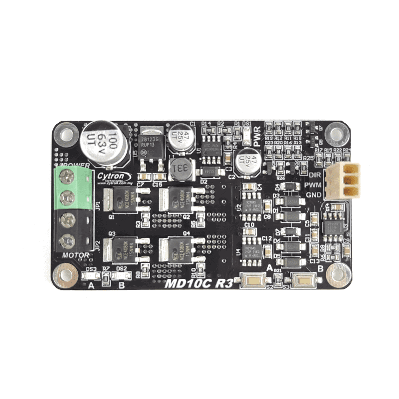
The Cytron MD10C Motor Driver is a versatile and robust module designed for controlling two brushed DC motors. It is widely used in robotics, automation projects, and various DIY applications where precise motor control is required. The driver operates within a voltage range of 5V to 30V, making it suitable for a wide array of motor types.
Explore Projects Built with Cytron MD10C Motor Driver


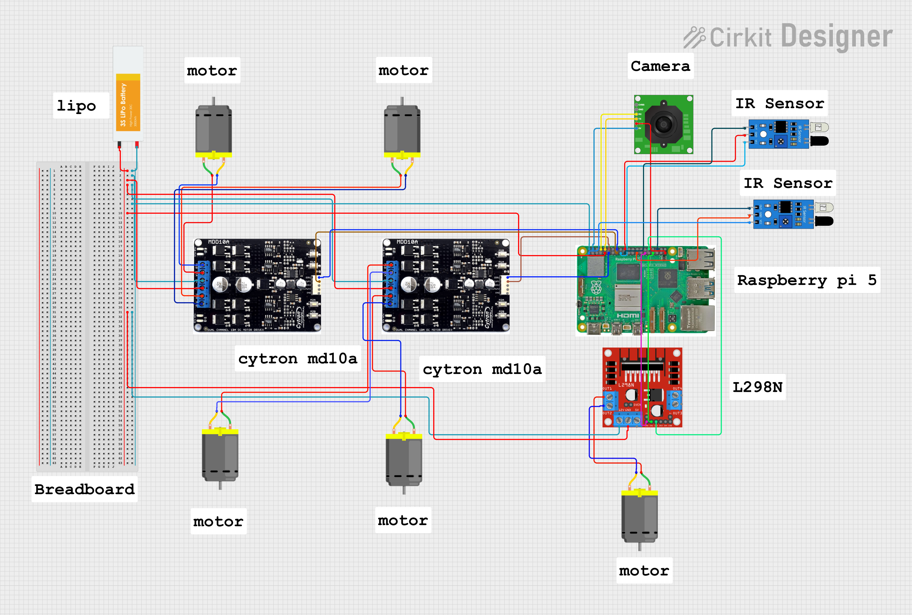
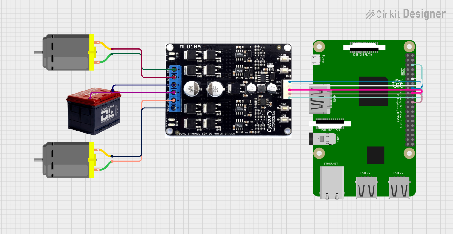
Explore Projects Built with Cytron MD10C Motor Driver
Common Applications and Use Cases
- Robotics
- Automated Guided Vehicles (AGVs)
- Hobbyist projects
- Educational platforms
- Prototyping motor control systems
Technical Specifications
Key Technical Details
- Motor Voltage (VM): 5V to 30V
- Continuous Current: Up to 13A
- Peak Current: Up to 30A (few seconds)
- Logic Voltage (Vcc): 3.3V to 5V
- PWM Duty Cycle: 0% to 100%
- Dimensions: 75mm x 43mm x 14mm
Pin Configuration and Descriptions
| Pin | Function | Description |
|---|---|---|
| VIN | Voltage Input | Connect to motor power supply (5V-30V) |
| GND | Ground | Connect to system and power ground |
| PWM | Pulse Width Modulation Input | Controls motor speed |
| DIR | Direction Input | Controls motor direction |
| BRK | Brake | Stops the motor when pulled HIGH |
| AN | Analog Input | Alternative to PWM for speed control |
| LIMIT | Current Limiting | Set current limit via potentiometer |
Usage Instructions
How to Use the Component in a Circuit
Power Connections:
- Connect the motor's power supply to the VIN and GND pins.
- Ensure the power supply voltage is within the specified range (5V-30V).
Motor Connections:
- Connect the two terminals of the motor to the output pins of the MD10C.
Control Connections:
- Connect the PWM pin to a PWM-capable pin on your microcontroller (e.g., Arduino).
- Connect the DIR pin to a digital output on your microcontroller to control direction.
- If using analog control, connect the AN pin to an analog output.
Logic Power:
- Supply the logic voltage (3.3V or 5V) to the Vcc pin from your microcontroller.
Brake and Current Limit:
- Connect the BRK pin to a digital output to enable the brake function.
- Adjust the onboard potentiometer to set the current limit as required.
Important Considerations and Best Practices
- Always ensure the power supply is disconnected before making any connections to the motor driver.
- Do not exceed the voltage and current ratings to prevent damage to the motor driver.
- Use appropriate heat sinks if operating the motor driver near its maximum current rating.
- Ensure proper ventilation around the motor driver to prevent overheating.
Example Code for Arduino UNO
// Define the pins connected to the MD10C
#define PWM_PIN 3
#define DIR_PIN 4

void setup() {
  // Set the motor control pins as outputs
  pinMode(PWM_PIN, OUTPUT);
  pinMode(DIR_PIN, OUTPUT);
}

void loop() {
  // Set motor direction to forward
  digitalWrite(DIR_PIN, HIGH);
  // Set motor speed to 50% duty cycle
  analogWrite(PWM_PIN, 128);
  delay(2000);

  // Set motor direction to reverse
  digitalWrite(DIR_PIN, LOW);
  // Set motor speed to 75% duty cycle
  analogWrite(PWM_PIN, 192);
  delay(2000);

  // Stop the motor
  digitalWrite(DIR_PIN, LOW);
  analogWrite(PWM_PIN, 0);
  delay(2000);
}
Troubleshooting and FAQs
Common Issues
- Motor not responding: Check power supply connections and ensure the logic voltage is supplied to Vcc.
- Overheating: Make sure the current does not exceed the continuous rating and that there is adequate cooling.
- Inconsistent motor speed: Verify that the PWM signal is within the correct duty cycle range.
Solutions and Tips for Troubleshooting
- Double-check all connections, especially the power supply and ground connections.
- Use a multimeter to verify the voltage levels at the power input and logic input pins.
- If the motor driver overheats, reduce the load or improve heat dissipation.
- Ensure the PWM frequency is compatible with the MD10C specifications.
FAQs
Q: Can I control the speed of the motor using an analog signal? A: Yes, you can use the AN pin to control the motor speed with an analog voltage.
Q: What is the maximum frequency for the PWM input? A: The MD10C can handle PWM frequencies up to 20kHz.
Q: How do I use the brake function? A: To engage the brake, set the BRK pin to a HIGH logic level. This will stop the motor immediately.
Q: Can I use the MD10C with a microcontroller that operates at 3.3V logic? A: Yes, the MD10C is compatible with both 3.3V and 5V logic levels.