
How to Use LCD screen: Examples, Pinouts, and Specs
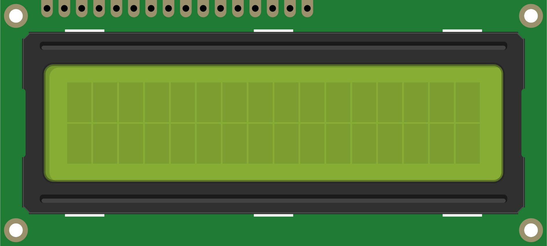
 Design with LCD screen in Cirkit Designer
Introduction
A liquid crystal display (LCD) screen is a flat-panel display technology that uses liquid crystals to produce images. It is widely used in televisions, computer monitors, portable devices, and embedded systems due to its lightweight, energy-efficient, and high-resolution capabilities. LCD screens are particularly popular in electronics projects for displaying text, numbers, and simple graphics.
Explore Projects Built with LCD screen
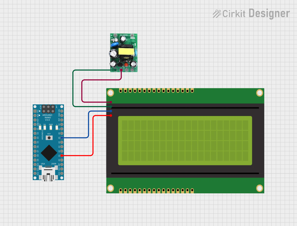 Open Project in Cirkit Designer
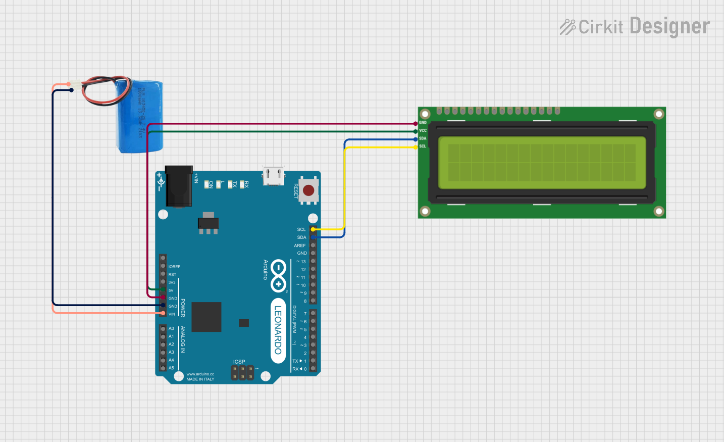 Open Project in Cirkit Designer
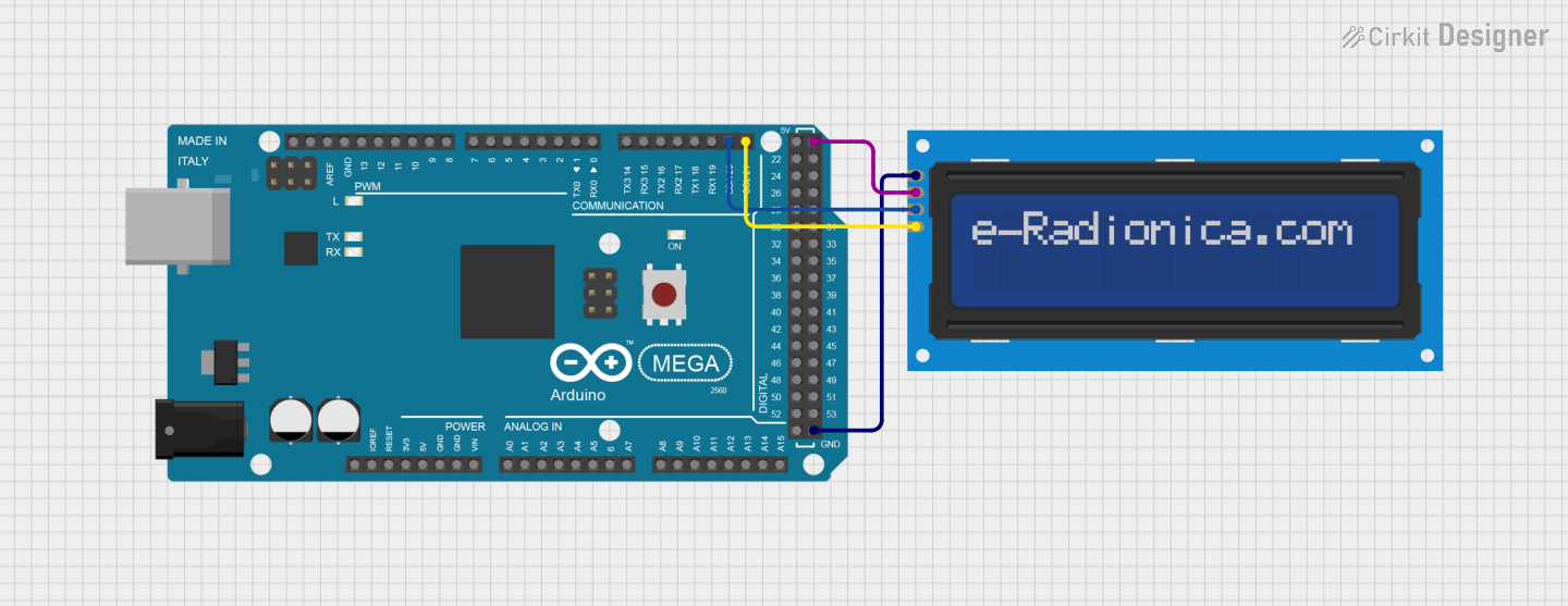 Open Project in Cirkit Designer
 Open Project in Cirkit Designer
Explore Projects Built with LCD screen
Open Project in Cirkit DesignerOpen Project in Cirkit DesignerOpen Project in Cirkit DesignerOpen Project in Cirkit DesignerCommon Applications and Use Cases
- Digital clocks and thermometers
- Embedded systems and microcontroller projects
- Portable devices such as calculators and handheld gaming consoles
- Industrial control panels
- Consumer electronics like televisions and monitors
Technical Specifications
Below are the general technical specifications for a standard 16x2 LCD screen (commonly used in electronics projects):
Key Technical Details
- Display Type: 16x2 (16 characters per row, 2 rows)
- Operating Voltage: 4.7V to 5.3V
- Current Consumption: 1mA (without backlight), 15mA (with backlight)
- Interface: Parallel (4-bit or 8-bit mode)
- Character Size: 5x8 dot matrix
- Backlight: LED (optional, typically white or green)
- Operating Temperature: -20°C to 70°C
Pin Configuration and Descriptions
The 16x2 LCD screen typically has 16 pins. Below is the pin configuration:
| Pin Number | Pin Name | Description |
|---|---|---|
| 1 | VSS | Ground (0V) connection |
| 2 | VDD | Power supply (4.7V to 5.3V) |
| 3 | V0 | Contrast adjustment (connect to a potentiometer) |
| 4 | RS | Register Select (0: Command mode, 1: Data mode) |
| 5 | RW | Read/Write (0: Write, 1: Read) |
| 6 | E | Enable pin (triggers data read/write) |
| 7 | D0 | Data pin 0 (used in 8-bit mode only) |
| 8 | D1 | Data pin 1 (used in 8-bit mode only) |
| 9 | D2 | Data pin 2 (used in 8-bit mode only) |
| 10 | D3 | Data pin 3 (used in 8-bit mode only) |
| 11 | D4 | Data pin 4 (used in both 4-bit and 8-bit modes) |
| 12 | D5 | Data pin 5 (used in both 4-bit and 8-bit modes) |
| 13 | D6 | Data pin 6 (used in both 4-bit and 8-bit modes) |
| 14 | D7 | Data pin 7 (used in both 4-bit and 8-bit modes) |
| 15 | LED+ | Backlight anode (connect to power through a resistor) |
| 16 | LED- | Backlight cathode (connect to ground) |
Usage Instructions
How to Use the Component in a Circuit
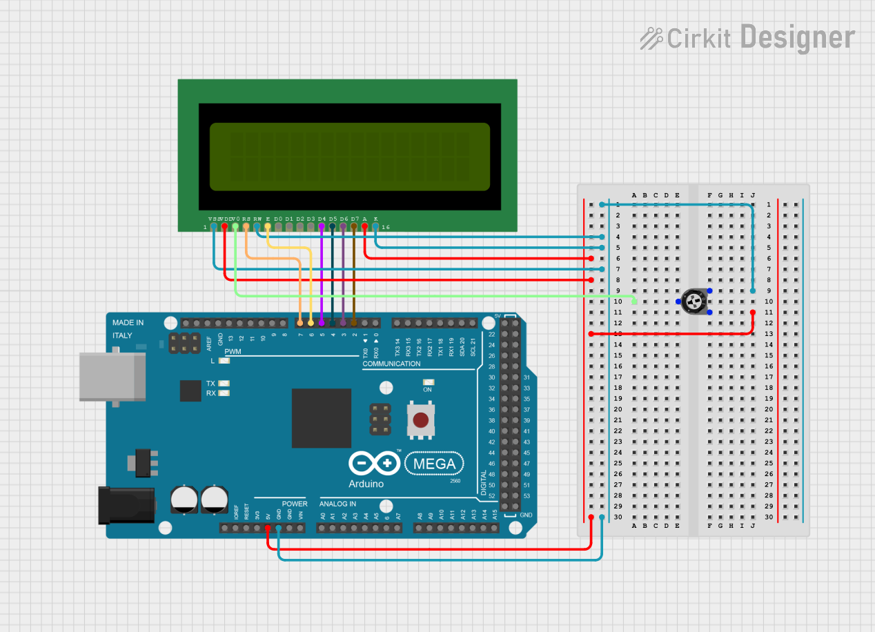
- Power the LCD: Connect the VSS pin to ground and the VDD pin to a 5V power supply.
- Adjust Contrast: Connect the V0 pin to the middle terminal of a 10kΩ potentiometer. Connect the other two terminals of the potentiometer to VDD and ground.
- Control Pins: Connect the RS, RW, and E pins to digital output pins of a microcontroller (e.g., Arduino).
- Data Pins: For 4-bit mode, connect D4 to D7 to the microcontroller. For 8-bit mode, connect D0 to D7.
- Backlight: Connect LED+ to 5V through a current-limiting resistor (e.g., 220Ω) and LED- to ground.
- Initialize the LCD: Use the appropriate library or code to initialize the LCD and send commands/data.
Important Considerations and Best Practices
- Always use a current-limiting resistor for the backlight to prevent damage.
- Use a 10kΩ potentiometer to adjust the contrast for optimal visibility.
- Ensure proper grounding to avoid noise or flickering issues.
- Use a library like
LiquidCrystalfor Arduino to simplify communication with the LCD.
Example Code for Arduino UNO
Below is an example of how to use a 16x2 LCD screen with an Arduino UNO in 4-bit mode:
#include <LiquidCrystal.h>

// Initialize the library with the pins connected to the LCD
// RS, E, D4, D5, D6, D7
LiquidCrystal lcd(12, 11, 5, 4, 3, 2);

void setup() {
  // Set up the LCD's number of columns and rows
  lcd.begin(16, 2);

  // Print a message to the LCD
  lcd.print("Hello, World!");
}

void loop() {
  // Move the cursor to the second row, first column
  lcd.setCursor(0, 1);

  // Print a dynamic message
  lcd.print("Count: ");
  lcd.print(millis() / 1000); // Display elapsed time in seconds
}
Notes:
- Connect the pins as specified in the
LiquidCrystalinitialization. - Ensure the Arduino is powered properly to avoid voltage drops.
Troubleshooting and FAQs
Common Issues and Solutions
No Display on the Screen
- Cause: Incorrect contrast setting.
- Solution: Adjust the potentiometer connected to the V0 pin.
Flickering or Unstable Display
- Cause: Poor grounding or unstable power supply.
- Solution: Ensure all ground connections are secure and use a decoupling capacitor near the power pins.
Backlight Not Working
- Cause: Missing or incorrect resistor for the backlight.
- Solution: Use a 220Ω resistor in series with the LED+ pin.
Incorrect Characters Displayed
- Cause: Data pins not properly connected or initialized.
- Solution: Double-check the wiring and ensure the LCD is initialized correctly in the code.
FAQs
Q: Can I use the LCD screen with a 3.3V microcontroller?
A: Yes, but you will need a level shifter or resistor divider for the data pins to avoid damaging the LCD.
Q: How do I display custom characters?
A: Use the createChar() function in the LiquidCrystal library to define and display custom characters.
Q: Can I use the LCD without a backlight?
A: Yes, the LCD will still function without a backlight, but visibility may be reduced in low-light conditions.
Q: What is the difference between 4-bit and 8-bit modes?
A: 4-bit mode uses fewer data pins (D4-D7) but requires more instructions to send data, while 8-bit mode uses all data pins (D0-D7) for faster communication.