Cirkit Designer Logo
Cirkit Designer
Your all-in-one circuit design IDE
Home / 
Component Documentation

How to Use ESP32 (30 pin): Examples, Pinouts, and Specs

Image of ESP32 (30 pin)
Cirkit Designer LogoDesign with ESP32 (30 pin) in Cirkit Designer

Introduction

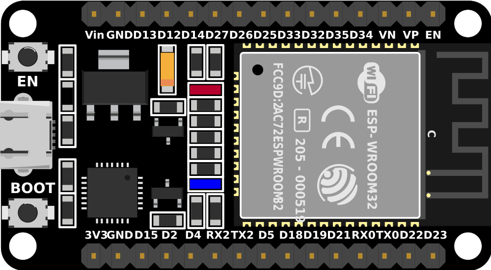
The ESP32 is a low-cost, low-power system on a chip (SoC) with integrated Wi-Fi and dual-mode Bluetooth. It features 30 GPIO pins, making it highly versatile for connectivity and control in various IoT applications. The ESP32 is widely used in smart home devices, wearables, industrial automation, and other embedded systems due to its robust performance and extensive feature set.

Explore Projects Built with ESP32 (30 pin)

Use Cirkit Designer to design, explore, and prototype these projects online. Some projects support real-time simulation. Click "Open Project" to start designing instantly!
ESP32-Based Smart Display with Camera and Audio Alert System
Image of cam_circuit_design: A project utilizing ESP32 (30 pin) in a practical application
This circuit features two ESP32 microcontrollers, one standard 30-pin version and one ESP32-CAM module, both sharing a common ground and power supply. The 30-pin ESP32 is interfaced with an I2C LCD 16x2 Screen for display purposes, using its I2C pins (D21 for SDA and D22 for SCL), and controls a buzzer connected to pin D23. Additionally, the ESP32-CAM is connected to the 30-pin ESP32 via serial communication through pins TX2 and RX2 for potential image data transfer.
Cirkit Designer LogoOpen Project in Cirkit Designer
ESP32-Based Environmental Monitoring System with Water Flow Sensing
Image of Water: A project utilizing ESP32 (30 pin) in a practical application
This circuit features an ESP32 Devkit V1 microcontroller connected to a DHT22 temperature and humidity sensor and a water flow sensor. The ESP32 reads environmental data from the DHT22 via a digital input pin (D33) and monitors water flow through the water flow sensor connected to another digital input pin (D23). The ESP32 is powered through its VIN pin, and both sensors are powered by the ESP32's 3V3 output, with common ground connections.
Cirkit Designer LogoOpen Project in Cirkit Designer
ESP32-Based OLED Display Interface
Image of d: A project utilizing ESP32 (30 pin) in a practical application
This circuit features an ESP32 microcontroller connected to an OLED 1.3" display. The ESP32's GPIO pins 21 and 22 are used for I2C communication (SDA and SCL respectively) with the OLED display. The display is powered by the 5V output from the ESP32, and both devices share a common ground.
Cirkit Designer LogoOpen Project in Cirkit Designer
ESP32-Based Environmental Monitoring System with OLED Display
Image of esproj: A project utilizing ESP32 (30 pin) in a practical application
This circuit features an ESP32 microcontroller as the central processing unit, interfacing with a DHT11 temperature and humidity sensor, an MPU-6050 accelerometer and gyroscope, an OLED display, and a separate temperature sensor. The ESP32 communicates with the MPU-6050 and the OLED display via I2C (using pins D22 and D21 for SCL and SDA, respectively), reads temperature data from the DHT11 sensor through pin D18, and interfaces with the additional temperature sensor via pin D5. All components share a common power supply connected to the ESP32's Vin pin and a common ground.
Cirkit Designer LogoOpen Project in Cirkit Designer

Explore Projects Built with ESP32 (30 pin)

Use Cirkit Designer to design, explore, and prototype these projects online. Some projects support real-time simulation. Click "Open Project" to start designing instantly!
Image of cam_circuit_design: A project utilizing ESP32 (30 pin) in a practical application
ESP32-Based Smart Display with Camera and Audio Alert System
This circuit features two ESP32 microcontrollers, one standard 30-pin version and one ESP32-CAM module, both sharing a common ground and power supply. The 30-pin ESP32 is interfaced with an I2C LCD 16x2 Screen for display purposes, using its I2C pins (D21 for SDA and D22 for SCL), and controls a buzzer connected to pin D23. Additionally, the ESP32-CAM is connected to the 30-pin ESP32 via serial communication through pins TX2 and RX2 for potential image data transfer.
Cirkit Designer LogoOpen Project in Cirkit Designer
Image of Water: A project utilizing ESP32 (30 pin) in a practical application
ESP32-Based Environmental Monitoring System with Water Flow Sensing
This circuit features an ESP32 Devkit V1 microcontroller connected to a DHT22 temperature and humidity sensor and a water flow sensor. The ESP32 reads environmental data from the DHT22 via a digital input pin (D33) and monitors water flow through the water flow sensor connected to another digital input pin (D23). The ESP32 is powered through its VIN pin, and both sensors are powered by the ESP32's 3V3 output, with common ground connections.
Cirkit Designer LogoOpen Project in Cirkit Designer
Image of d: A project utilizing ESP32 (30 pin) in a practical application
ESP32-Based OLED Display Interface
This circuit features an ESP32 microcontroller connected to an OLED 1.3" display. The ESP32's GPIO pins 21 and 22 are used for I2C communication (SDA and SCL respectively) with the OLED display. The display is powered by the 5V output from the ESP32, and both devices share a common ground.
Cirkit Designer LogoOpen Project in Cirkit Designer
Image of esproj: A project utilizing ESP32 (30 pin) in a practical application
ESP32-Based Environmental Monitoring System with OLED Display
This circuit features an ESP32 microcontroller as the central processing unit, interfacing with a DHT11 temperature and humidity sensor, an MPU-6050 accelerometer and gyroscope, an OLED display, and a separate temperature sensor. The ESP32 communicates with the MPU-6050 and the OLED display via I2C (using pins D22 and D21 for SCL and SDA, respectively), reads temperature data from the DHT11 sensor through pin D18, and interfaces with the additional temperature sensor via pin D5. All components share a common power supply connected to the ESP32's Vin pin and a common ground.
Cirkit Designer LogoOpen Project in Cirkit Designer

Technical Specifications

Key Technical Details

Parameter Value
Operating Voltage 3.3V
Input Voltage 5V (via USB)
Digital I/O Pins 30
Analog Input Pins 16 (12-bit ADC)
Flash Memory 4MB (varies by model)
SRAM 520KB
Wi-Fi Standards 802.11 b/g/n
Bluetooth v4.2 BR/EDR and BLE
CPU Dual-core 32-bit LX6 microprocessor
Clock Speed Up to 240 MHz
Operating Temperature -40°C to 125°C

Pin Configuration and Descriptions

Pin Number Pin Name Description
1 EN Enable (Active High)
2 IO23 GPIO23, ADC2_CH0, HSPI MOSI
3 IO22 GPIO22, ADC2_CH1, HSPI CLK
4 IO1 GPIO1, UART0 TX
5 IO3 GPIO3, UART0 RX
6 IO21 GPIO21, I2C SDA
7 GND Ground
8 IO19 GPIO19, ADC2_CH3, VSPI MISO
9 IO18 GPIO18, ADC2_CH4, VSPI CLK
10 IO5 GPIO5, ADC2_CH5, VSPI CS0
11 IO17 GPIO17, UART2 TX
12 IO16 GPIO16, UART2 RX
13 IO4 GPIO4, ADC2_CH0, HSPI CS0
14 IO0 GPIO0, ADC2_CH1, Boot Button
15 IO2 GPIO2, ADC2_CH2, HSPI WP
16 IO15 GPIO15, ADC2_CH3, HSPI CS1
17 IO13 GPIO13, ADC2_CH4, HSPI ID
18 IO12 GPIO12, ADC2_CH5, HSPI Q
19 IO14 GPIO14, ADC2_CH6, HSPI CLK
20 IO27 GPIO27, ADC2_CH7, HSPI D
21 IO26 GPIO26, ADC2_CH8, HSPI D
22 IO25 GPIO25, ADC2_CH9, HSPI D
23 IO33 GPIO33, ADC1_CH5, DAC1
24 IO32 GPIO32, ADC1_CH4, DAC1
25 IO35 GPIO35, ADC1_CH7
26 IO34 GPIO34, ADC1_CH6
27 IO39 GPIO39, ADC1_CH3
28 IO36 GPIO36, ADC1_CH0
29 IO37 GPIO37, ADC1_CH1
30 IO38 GPIO38, ADC1_CH2

Usage Instructions

How to Use the ESP32 in a Circuit

  1. Powering the ESP32:

    • Connect the 5V pin to a 5V power source (e.g., USB).
    • Ensure the GND pin is connected to the ground of the power source.
  2. Programming the ESP32:

    • Use the UART0 TX (IO1) and UART0 RX (IO3) pins for serial communication.
    • Connect the EN pin to a high signal to enable the chip.
  3. Connecting Peripherals:

    • Use the GPIO pins for digital I/O operations.
    • Utilize the ADC pins for analog input.
    • Connect I2C devices to IO21 (SDA) and IO22 (SCL).
    • Use SPI pins (e.g., IO23, IO19, IO18) for SPI communication.

Important Considerations and Best Practices

  • Voltage Levels: Ensure all connected devices operate at 3.3V logic levels to avoid damaging the ESP32.
  • Power Supply: Use a stable power supply to prevent brownouts and ensure reliable operation.
  • Pin Multiplexing: Be aware of the multiple functions of each pin and avoid conflicts in your design.
  • Heat Management: Ensure adequate ventilation or heat sinking if operating at high loads or in warm environments.

Troubleshooting and FAQs

Common Issues

  1. ESP32 Not Powering On:

    • Check the power connections and ensure the EN pin is high.
    • Verify the power supply voltage is within the acceptable range.
  2. Wi-Fi Connection Issues:

    • Ensure the correct SSID and password are used.
    • Check for interference from other devices.
  3. Serial Communication Problems:

    • Verify the correct baud rate is set in the serial monitor.
    • Ensure the TX and RX pins are correctly connected.

Solutions and Tips for Troubleshooting

  • Resetting the ESP32:

    • Press the reset button or toggle the EN pin to reset the device.
  • Debugging Code:

    • Use serial print statements to debug and monitor the code execution.
  • Firmware Updates:

    • Ensure the latest firmware is installed to benefit from bug fixes and improvements.

Example Code for Arduino UNO

#include <WiFi.h>

// Replace with your network credentials
const char* ssid = "your_SSID";
const char* password = "your_PASSWORD";

void setup() {
  Serial.begin(115200); // Initialize serial communication at 115200 baud
  delay(10);

  // Connect to Wi-Fi network
  Serial.println();
  Serial.print("Connecting to ");
  Serial.println(ssid);

  WiFi.begin(ssid, password);

  while (WiFi.status() != WL_CONNECTED) {
    delay(500);
    Serial.print(".");
  }

  Serial.println("");
  Serial.println("WiFi connected.");
  Serial.println("IP address: ");
  Serial.println(WiFi.localIP()); // Print the IP address
}

void loop() {
  // Your main code here
}

This example demonstrates how to connect the ESP32 to a Wi-Fi network using the Arduino IDE. Replace your_SSID and your_PASSWORD with your network credentials.

By following this documentation, users can effectively utilize the ESP32 in their projects, troubleshoot common issues, and implement best practices for reliable operation.