Cirkit Designer Logo
Cirkit Designer
Your all-in-one circuit design IDE
Home / 
Component Documentation

How to Use USB male 2 pin connection: Examples, Pinouts, and Specs

Image of USB male 2 pin connection
Cirkit Designer LogoDesign with USB male 2 pin connection in Cirkit Designer

Introduction

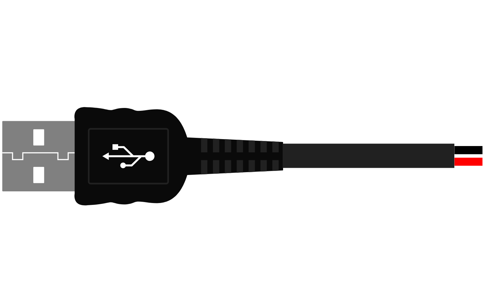
The USB Male 2-Pin Connection is a simplified USB connector that is designed to provide power supply and basic data transfer capabilities. It is a streamlined version of the standard USB interface, which typically has four or more pins. This connector is commonly used in applications where only power and a single data line are required, such as in some LED lighting applications, basic microcontroller interfaces, or charging devices.

Explore Projects Built with USB male 2 pin connection

Use Cirkit Designer to design, explore, and prototype these projects online. Some projects support real-time simulation. Click "Open Project" to start designing instantly!
USB-Powered Pushbutton Controlled LED Circuit
Image of oppgv. 10: A project utilizing USB male 2 pin connection in a practical application
This circuit consists of a USB power converter supplying power to three pushbuttons, each connected to a corresponding red LED. When a button is pressed, it closes the circuit for its associated LED, causing the LED to light up. The common ground for the circuit is provided through a 40-pin connector, which also serves as an interface for the pushbuttons' inputs and the LEDs' cathodes.
Cirkit Designer LogoOpen Project in Cirkit Designer
Pushbutton-Controlled Interface with 40-Pin Connector and UBS Power Supply
Image of connect 4: A project utilizing USB male 2 pin connection in a practical application
This circuit consists of a 40-pin connector interfacing with four pushbuttons and a UBS power supply. The pushbuttons are used as inputs to the connector, which then relays the signals to other components or systems. The UBS power supply provides the necessary 24V power to the pushbuttons and the common ground for the circuit.
Cirkit Designer LogoOpen Project in Cirkit Designer
USB Type-C Powered LED Circuit with Resistor
Image of Scheme1: A project utilizing USB male 2 pin connection in a practical application
This circuit consists of a USB Type-C port providing power to a red LED through a 1000 Ohm resistor. The resistor limits the current flowing through the LED, which lights up when the circuit is powered.
Cirkit Designer LogoOpen Project in Cirkit Designer
5-Pin Connector Synchronization Circuit
Image of UMB_Cable: A project utilizing USB male 2 pin connection in a practical application
This circuit consists of four 5-pin connectors, where two of the connectors are fully interconnected pin-to-pin. The purpose of this setup could be to create a parallel connection between the two 5-pin connectors, possibly for signal distribution or redundancy.
Cirkit Designer LogoOpen Project in Cirkit Designer

Explore Projects Built with USB male 2 pin connection

Use Cirkit Designer to design, explore, and prototype these projects online. Some projects support real-time simulation. Click "Open Project" to start designing instantly!
Image of oppgv. 10: A project utilizing USB male 2 pin connection in a practical application
USB-Powered Pushbutton Controlled LED Circuit
This circuit consists of a USB power converter supplying power to three pushbuttons, each connected to a corresponding red LED. When a button is pressed, it closes the circuit for its associated LED, causing the LED to light up. The common ground for the circuit is provided through a 40-pin connector, which also serves as an interface for the pushbuttons' inputs and the LEDs' cathodes.
Cirkit Designer LogoOpen Project in Cirkit Designer
Image of connect 4: A project utilizing USB male 2 pin connection in a practical application
Pushbutton-Controlled Interface with 40-Pin Connector and UBS Power Supply
This circuit consists of a 40-pin connector interfacing with four pushbuttons and a UBS power supply. The pushbuttons are used as inputs to the connector, which then relays the signals to other components or systems. The UBS power supply provides the necessary 24V power to the pushbuttons and the common ground for the circuit.
Cirkit Designer LogoOpen Project in Cirkit Designer
Image of Scheme1: A project utilizing USB male 2 pin connection in a practical application
USB Type-C Powered LED Circuit with Resistor
This circuit consists of a USB Type-C port providing power to a red LED through a 1000 Ohm resistor. The resistor limits the current flowing through the LED, which lights up when the circuit is powered.
Cirkit Designer LogoOpen Project in Cirkit Designer
Image of UMB_Cable: A project utilizing USB male 2 pin connection in a practical application
5-Pin Connector Synchronization Circuit
This circuit consists of four 5-pin connectors, where two of the connectors are fully interconnected pin-to-pin. The purpose of this setup could be to create a parallel connection between the two 5-pin connectors, possibly for signal distribution or redundancy.
Cirkit Designer LogoOpen Project in Cirkit Designer

Common Applications and Use Cases

  • Powering small electronic devices via USB ports
  • Charging batteries in portable devices
  • Providing power to microcontroller boards (e.g., Arduino)
  • Simple data transfer where only one data line is necessary

Technical Specifications

Key Technical Details

  • Voltage Rating: Typically 5V (as per standard USB specification)
  • Current Rating: Up to 1A (depending on cable and connector quality)
  • Data Transfer Rate: Limited by the single data line implementation

Pin Configuration and Descriptions

Pin Number Description Notes
1 VBUS (Power Supply) Typically provides +5V
2 Data- or Data+ Single data line for basic transfer

Note: The actual pinout may vary based on specific implementation and should be verified with the manufacturer's datasheet.

Usage Instructions

How to Use the Component in a Circuit

  1. Power Connection:

    • Connect Pin 1 (VBUS) to the power input of your device.
    • Ensure that the device can operate at 5V, which is the standard USB voltage.
  2. Data Connection:

    • Connect Pin 2 to the data input or output of your device.
    • If the device requires a specific data line (Data+ or Data-), ensure that the correct line is connected.

Important Considerations and Best Practices

  • Voltage Regulation: Ensure that your device has proper voltage regulation if it cannot handle 5V directly.
  • Current Limitation: Do not exceed the current rating of the connector to avoid damage.
  • Data Line Protection: Implement necessary protection on the data line, such as a series resistor or a clamping diode, to protect against voltage spikes.
  • Cable Quality: Use a cable that can handle the required current for your application.

Troubleshooting and FAQs

Common Issues Users Might Face

  • Device Not Powering On: Check the connection of the VBUS pin and ensure the USB port is supplying power.
  • Data Transfer Not Working: Verify that the data line is connected properly and that the device is configured to communicate using the single data line available.

Solutions and Tips for Troubleshooting

  • Check Connections: Ensure all connections are secure and properly soldered.
  • Test with Another USB Port: Some USB ports may not provide power; try a different port.
  • Use a Multimeter: Check for continuity and correct voltage levels on the VBUS pin.

FAQs

  • Q: Can I use this connector for USB data transfer?

    • A: Yes, but it will be limited to basic data transfer due to the single data line.
  • Q: Is this connector compatible with all USB ports?

    • A: It should be compatible with USB ports for power, but data compatibility will depend on the device and application.

Example Code for Arduino UNO

// This example assumes the USB Male 2-Pin Connection is used to power the Arduino and provide a basic data signal.

void setup() {
  pinMode(2, INPUT); // Assuming data is connected to digital pin 2
  Serial.begin(9600); // Start serial communication at 9600 baud rate
}

void loop() {
  int dataValue = digitalRead(2); // Read the data from the USB connection
  Serial.println(dataValue); // Print the data value to the Serial Monitor
  delay(1000); // Wait for 1 second before reading the data again
}

Note: The above code is a simple demonstration of reading a digital signal from the USB Male 2-Pin Connection. The actual implementation will vary based on the specific application and device requirements.

Remember to always refer to the specific datasheet of the USB Male 2-Pin Connection you are using for accurate pinout and specifications.