How to Use Arduino Due: Examples, Pinouts, and Specs
Introduction
The Arduino Due is a powerful microcontroller board based on the Atmel SAM3X8E ARM Cortex-M3 processor. It is designed for high-performance applications and rapid prototyping, offering advanced features compared to other Arduino boards. With 54 digital input/output pins, 12 analog inputs, and USB connectivity, the Arduino Due is ideal for projects requiring significant processing power, precision, and flexibility.
Explore Projects Built with Arduino Due
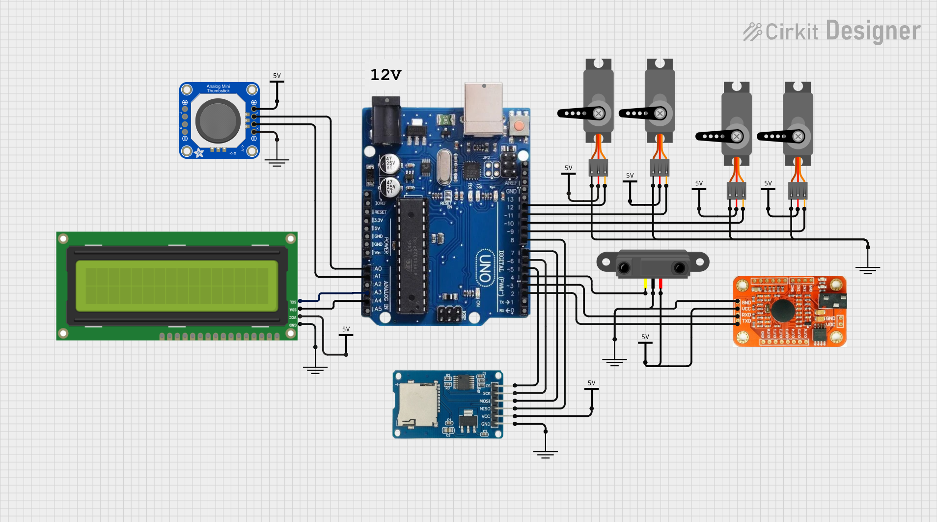
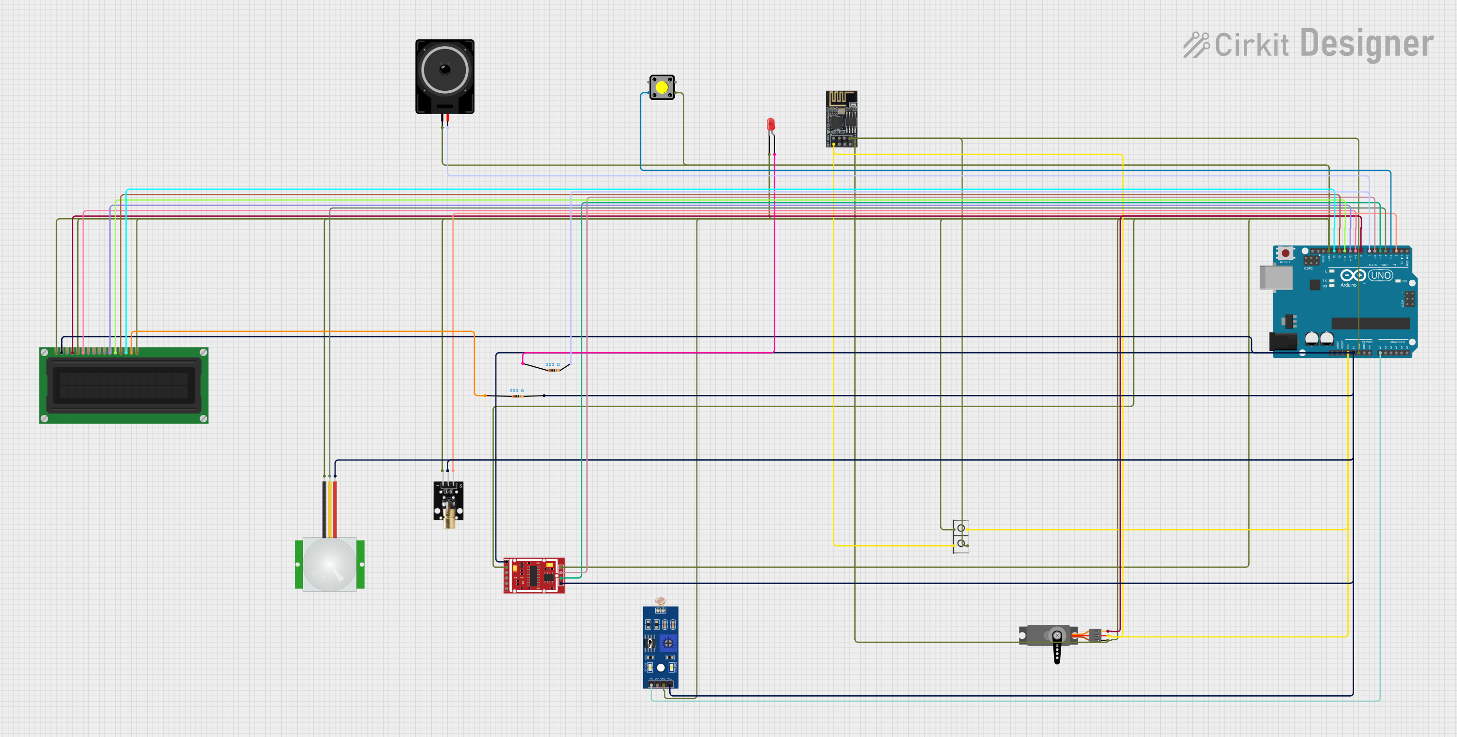
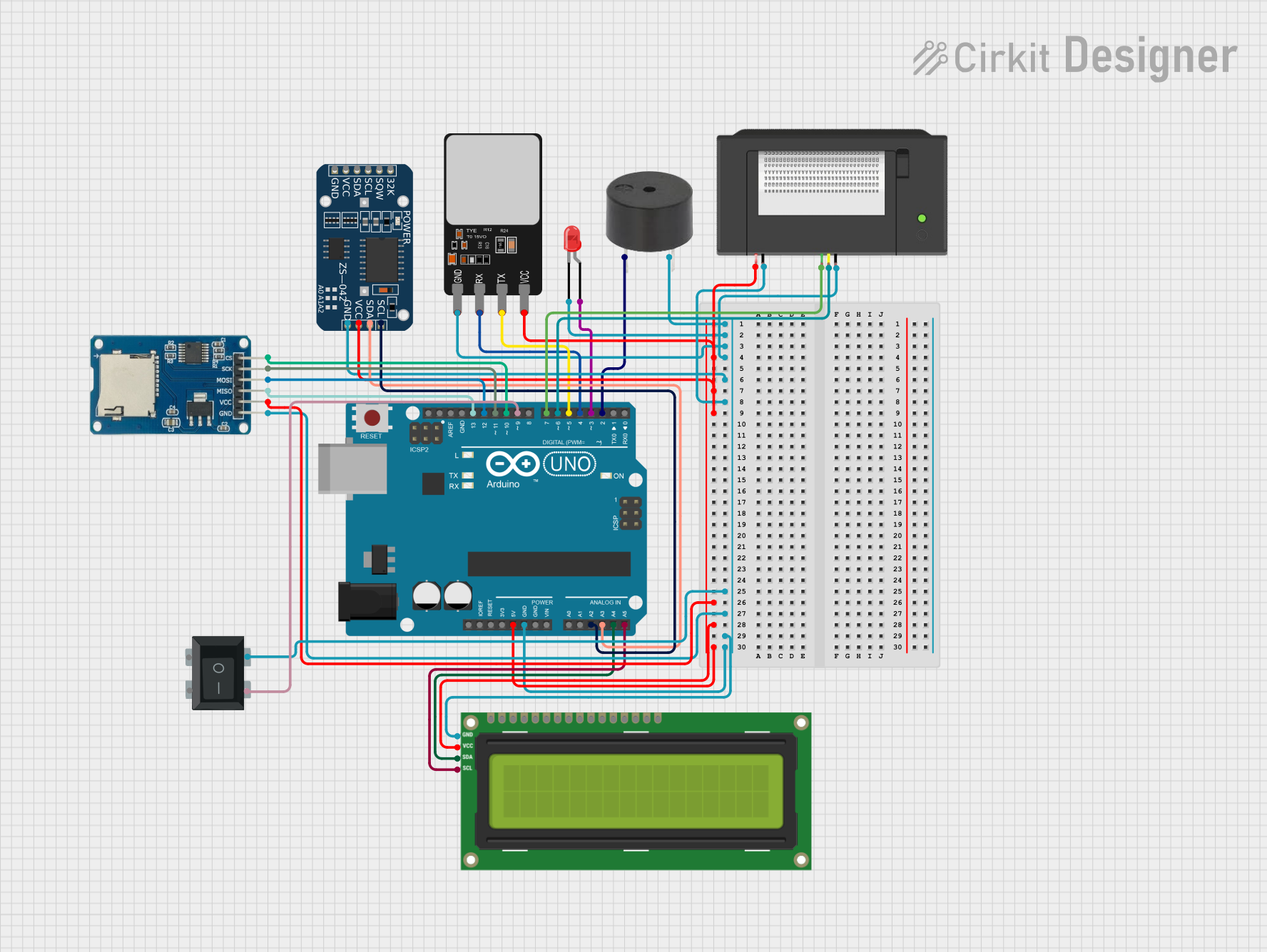
Explore Projects Built with Arduino Due
Common Applications and Use Cases
- Robotics and automation systems
- Data acquisition and processing
- High-speed communication interfaces
- Audio processing and synthesis
- Advanced IoT (Internet of Things) applications
- Complex sensor networks
Technical Specifications
Below are the key technical details of the Arduino Due:
| Specification | Details |
|---|---|
| Microcontroller | Atmel SAM3X8E ARM Cortex-M3 |
| Operating Voltage | 3.3V |
| Input Voltage (recommended) | 7-12V |
| Input Voltage (limit) | 6-20V |
| Digital I/O Pins | 54 (12 of which support PWM output) |
| Analog Input Pins | 12 |
| Analog Output Pins | 2 (DAC) |
| DC Current per I/O Pin | 130 mA |
| Flash Memory | 512 KB (of which 96 KB is used by the bootloader) |
| SRAM | 96 KB (split into two banks: 64 KB and 32 KB) |
| Clock Speed | 84 MHz |
| USB Connectivity | Native USB and Programming USB ports |
| Dimensions | 101.52 mm x 53.3 mm |
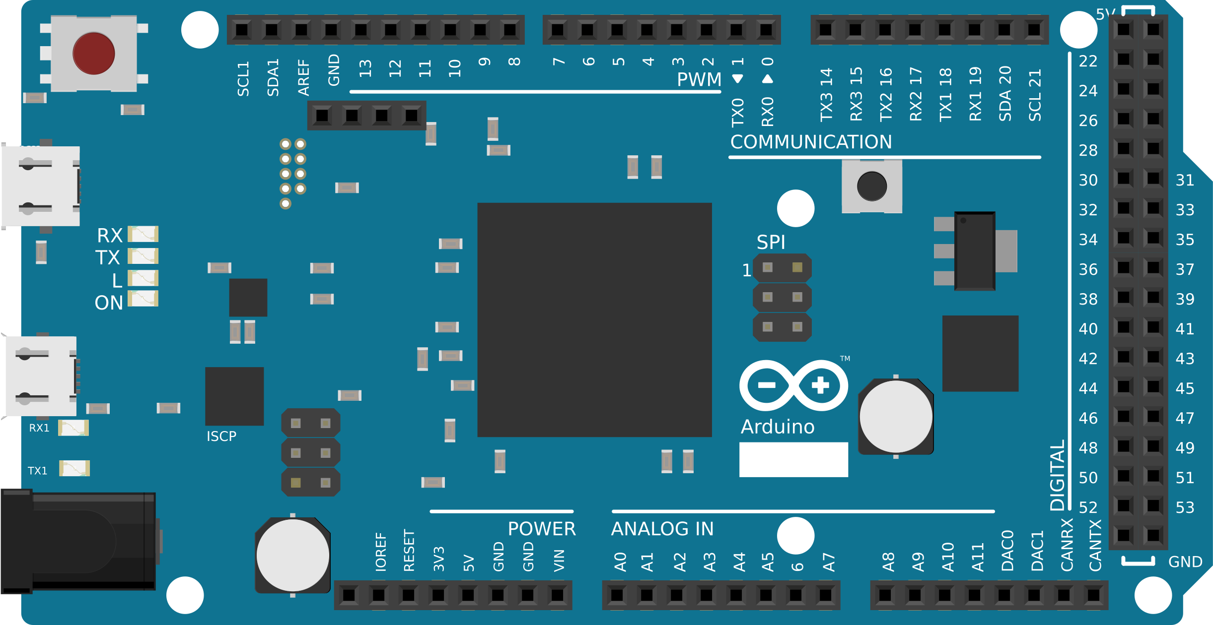
Pin Configuration and Descriptions
The Arduino Due has a variety of pins for different functionalities. Below is a summary:
Digital Pins
| Pin Number | Functionality |
|---|---|
| 0-1 | UART (Serial Communication) |
| 2-13 | General-purpose digital I/O |
| 11, 12, 13 | SPI (MOSI, MISO, SCK) |
| 2, 3, 5, 6, 7, 8 | PWM output |
| 20-21 | I2C (SDA, SCL) |
Analog Pins
| Pin Number | Functionality |
|---|---|
| A0-A11 | Analog inputs (12-bit resolution) |
| DAC0, DAC1 | Analog outputs (10-bit resolution) |
Power Pins
| Pin Name | Description |
|---|---|
| VIN | Input voltage to the board (7-12V) |
| 3.3V | Regulated 3.3V output |
| 5V | Regulated 5V output |
| GND | Ground |
| IOREF | Reference voltage for I/O pins |
Usage Instructions
The Arduino Due is straightforward to use but requires attention to its 3.3V operating voltage, as applying 5V to its pins can damage the board.
How to Use the Arduino Due in a Circuit
Powering the Board:
- Use the USB port for programming and powering the board during development.
- For standalone applications, supply 7-12V to the VIN pin or the DC power jack.
Connecting Components:
- Ensure all components connected to the I/O pins operate at 3.3V logic levels.
- Use level shifters if interfacing with 5V devices.
Programming the Board:
- Connect the board to your computer using the Programming USB port.
- Select "Arduino Due (Programming Port)" in the Arduino IDE under Tools > Board.
- Write and upload your code.
Example Code: Blinking an LED
The following example demonstrates how to blink an LED connected to pin 13:
// Blink an LED connected to pin 13 on the Arduino Due
void setup() {
  pinMode(13, OUTPUT); // Set pin 13 as an output
}

void loop() {
  digitalWrite(13, HIGH); // Turn the LED on
  delay(1000);            // Wait for 1 second
  digitalWrite(13, LOW);  // Turn the LED off
  delay(1000);            // Wait for 1 second
}
Important Considerations and Best Practices
- Voltage Levels: The Arduino Due operates at 3.3V. Avoid applying 5V to any pin.
- USB Ports: Use the Native USB port for USB host applications and the Programming USB port for uploading sketches.
- Current Limits: Do not exceed 130 mA per I/O pin to prevent damage.
- Analog Inputs: The analog inputs have a maximum input voltage of 3.3V. Use a voltage divider if necessary.
Troubleshooting and FAQs
Common Issues and Solutions
The board is not recognized by the computer:
- Ensure the correct USB cable is used (some cables are power-only).
- Check that the drivers for the Arduino Due are installed.
- Try using a different USB port or computer.
Sketch upload fails:
- Verify that the correct board and port are selected in the Arduino IDE.
- Use the Programming USB port for uploading sketches.
- Press the "Erase" button on the board, followed by the "Reset" button, and try uploading again.
Connected components are not working:
- Confirm that all components are compatible with 3.3V logic levels.
- Double-check wiring and connections.
The board overheats:
- Ensure the input voltage does not exceed 12V.
- Check for short circuits in the connected circuit.
FAQs
Q: Can I use 5V sensors with the Arduino Due?
A: Yes, but you must use a level shifter to convert the 5V signals to 3.3V to avoid damaging the board.
Q: What is the difference between the Native USB and Programming USB ports?
A: The Native USB port supports USB host functionality and higher-speed communication, while the Programming USB port is used for uploading sketches and debugging.
Q: How do I reset the Arduino Due?
A: Press the "Reset" button on the board. For a full reset, press the "Erase" button followed by the "Reset" button.
By following this documentation, you can effectively utilize the Arduino Due for your high-performance projects and prototyping needs.