How to Use COB LED Driver Board for Seeed Studio XIAO: Examples, Pinouts, and Specs
Introduction
The COB LED Driver Board for Seeed Studio XIAO is a compact and efficient driver designed to power Chip-on-Board (COB) LEDs. It is specifically tailored to work seamlessly with the Seeed Studio XIAO microcontroller platform, enabling precise control and operation of high-brightness LED arrays. This driver board simplifies the integration of COB LEDs into projects, making it ideal for applications requiring high-intensity lighting with minimal power loss.
Explore Projects Built with COB LED Driver Board for Seeed Studio XIAO
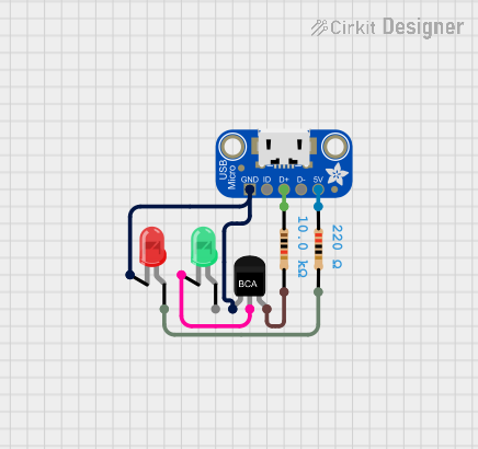

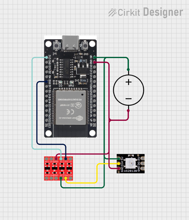

Explore Projects Built with COB LED Driver Board for Seeed Studio XIAO
Common Applications and Use Cases
- Smart lighting systems
- Wearable devices with high-brightness LEDs
- IoT projects requiring efficient LED control
- Photography and videography lighting
- Prototyping and development of LED-based designs
Technical Specifications
Key Technical Details
- Input Voltage: 3.3V to 5V DC (compatible with Seeed Studio XIAO power supply)
- Output Voltage: 9V to 12V DC (suitable for COB LEDs)
- Output Current: Up to 500mA (constant current)
- Efficiency: >90% (depending on input/output conditions)
- Control Interface: PWM (Pulse Width Modulation) via Seeed Studio XIAO
- Dimensions: 25mm x 20mm x 5mm
- Operating Temperature: -20°C to 70°C
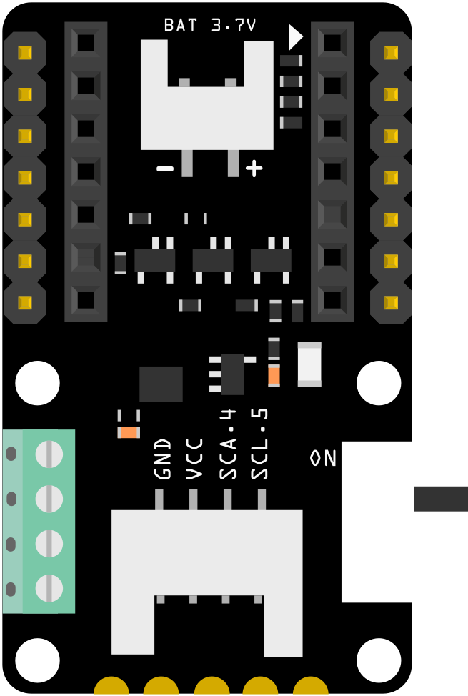
Pin Configuration and Descriptions
The COB LED Driver Board has the following pin configuration:
| Pin Name | Description |
|---|---|
| VIN | Input voltage (3.3V to 5V DC). Connect to the 3.3V or 5V pin of the XIAO. |
| GND | Ground connection. Connect to the GND pin of the XIAO. |
| PWM | PWM input signal for brightness control. Connect to a PWM-capable pin on XIAO. |
| LED+ | Positive terminal for the COB LED. |
| LED- | Negative terminal for the COB LED. |
Usage Instructions
How to Use the Component in a Circuit
- Power Connection: Connect the VIN pin of the driver board to the 3.3V or 5V output of the Seeed Studio XIAO. Connect the GND pin to the ground of the XIAO.
- PWM Control: Connect the PWM pin of the driver board to a PWM-capable pin on the XIAO (e.g., D3 or D5). This pin will control the brightness of the COB LED.
- LED Connection: Connect the COB LED's positive terminal to the LED+ pin and the negative terminal to the LED- pin on the driver board.
- Programming: Use the XIAO to generate a PWM signal to control the brightness of the COB LED. The duty cycle of the PWM signal determines the brightness level.
Important Considerations and Best Practices
- Ensure the input voltage to the driver board matches the operating voltage of the XIAO (3.3V or 5V).
- Use a heatsink or proper ventilation for the COB LED to prevent overheating.
- Avoid exceeding the maximum output current (500mA) to prevent damage to the driver board or LED.
- Use a multimeter to verify connections before powering the circuit.
- For optimal performance, ensure the PWM frequency is set between 500Hz and 1kHz.
Example Code for Arduino UNO-Compatible Seeed Studio XIAO
Below is an example code snippet to control the brightness of a COB LED using the PWM pin of the Seeed Studio XIAO:
// Define the PWM pin connected to the COB LED Driver Board
const int pwmPin = 3; // Use a PWM-capable pin on the XIAO

void setup() {
  // Set the PWM pin as an output
  pinMode(pwmPin, OUTPUT);
}

void loop() {
  // Gradually increase brightness
  for (int brightness = 0; brightness <= 255; brightness++) {
    analogWrite(pwmPin, brightness); // Write PWM signal to the driver board
    delay(10); // Small delay for smooth transition
  }

  // Gradually decrease brightness
  for (int brightness = 255; brightness >= 0; brightness--) {
    analogWrite(pwmPin, brightness); // Write PWM signal to the driver board
    delay(10); // Small delay for smooth transition
  }
}
Troubleshooting and FAQs
Common Issues and Solutions
The COB LED does not light up:
- Solution: Verify all connections, especially the VIN, GND, LED+, and LED- pins. Ensure the input voltage is within the specified range (3.3V to 5V).
- Tip: Check the polarity of the COB LED. Reversing the LED+ and LED- connections will prevent the LED from lighting up.
The COB LED flickers:
- Solution: Ensure the PWM frequency is set between 500Hz and 1kHz. Flickering may occur if the frequency is too low.
- Tip: Use a stable power supply to avoid voltage fluctuations.
The driver board overheats:
- Solution: Check if the COB LED's current exceeds 500mA. Use a heatsink for the COB LED to dissipate heat effectively.
- Tip: Reduce the duty cycle of the PWM signal to lower the LED's brightness and power consumption.
The brightness control is not smooth:
- Solution: Ensure the PWM signal is properly configured in the code. Use a gradual increase or decrease in the duty cycle for smooth transitions.
- Tip: Test the circuit with a multimeter to confirm the PWM signal is being output correctly.
FAQs
Q: Can I use this driver board with other microcontrollers?
A: Yes, the driver board can be used with any microcontroller that supports PWM output and operates at 3.3V or 5V logic levels.
Q: What type of COB LEDs are compatible with this driver board?
A: The driver board is compatible with COB LEDs requiring 9V to 12V DC and a maximum current of 500mA.
Q: Can I power multiple COB LEDs with this driver board?
A: No, the driver board is designed to power a single COB LED. For multiple LEDs, use additional driver boards or a higher-capacity driver.
Q: What is the recommended PWM frequency for brightness control?
A: A PWM frequency between 500Hz and 1kHz is recommended for optimal performance and minimal flicker.