How to Use adxl345: Examples, Pinouts, and Specs
Introduction
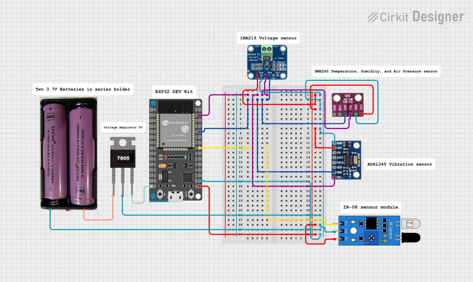
The ADXL345 is a small, thin, low-power, 3-axis accelerometer manufactured by Arduino with the part ID "UNO". It provides high-resolution (13-bit) measurements of acceleration up to ±16g. The device features a digital output accessible via I2C or SPI interfaces, making it versatile and easy to integrate into a wide range of applications.
Explore Projects Built with adxl345
Explore Projects Built with adxl345
Common Applications and Use Cases
- Motion sensing in portable devices
- Tilt detection for user interface control
- Gesture recognition in gaming and robotics
- Vibration monitoring in industrial systems
- Fall detection in healthcare devices
Technical Specifications
The ADXL345 is designed for precision and flexibility, with the following key specifications:
| Parameter | Value |
|---|---|
| Measurement Range | ±2g, ±4g, ±8g, ±16g |
| Resolution | 13-bit |
| Supply Voltage (VDD) | 2.0V to 3.6V |
| Interface | I2C or SPI |
| Operating Temperature | -40°C to +85°C |
| Power Consumption | 40 µA in measurement mode |
| Output Data Rate (ODR) | 0.1 Hz to 3200 Hz |
| Dimensions | 3 mm × 5 mm × 1 mm |
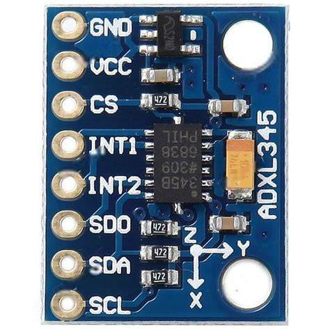
Pin Configuration and Descriptions
The ADXL345 has 8 pins, as described in the table below:
| Pin | Name | Description |
|---|---|---|
| 1 | VDD | Power supply input (2.0V to 3.6V). |
| 2 | GND | Ground connection. |
| 3 | CS | Chip Select: Used to select SPI mode (active low). Tie high for I2C mode. |
| 4 | INT1 | Interrupt 1: Configurable interrupt output. |
| 5 | INT2 | Interrupt 2: Configurable interrupt output. |
| 6 | SCL/SCLK | Serial Clock: I2C clock line or SPI clock input. |
| 7 | SDA/SDI | Serial Data: I2C data line or SPI data input. |
| 8 | SDO/ALT | SPI data output or I2C alternate address select. Tie low for default I2C address. |
Usage Instructions
The ADXL345 can be used in either I2C or SPI mode, depending on the application. Below are the steps to integrate the ADXL345 into a circuit and communicate with it using an Arduino UNO.
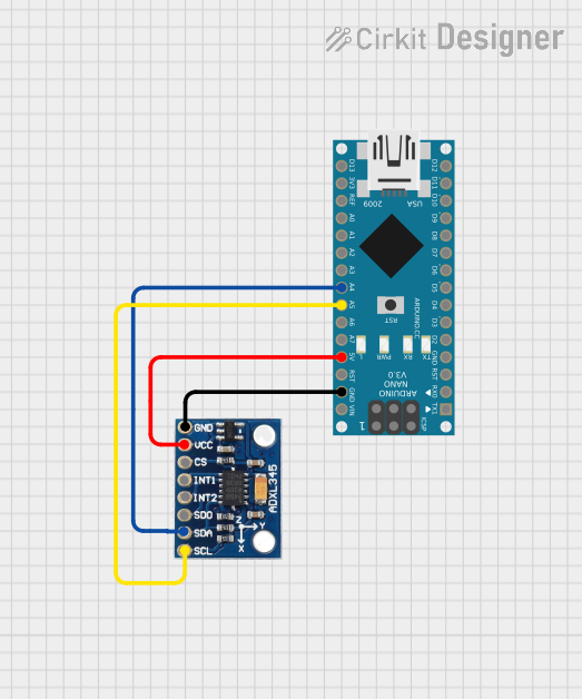
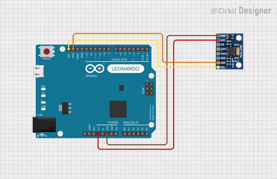
Connecting the ADXL345 to an Arduino UNO (I2C Mode)
Wiring:
- Connect the ADXL345's
VDDpin to the Arduino's3.3Vpin. - Connect the
GNDpin to the Arduino'sGND. - Connect the
SCLpin to the Arduino'sA5pin (I2C clock line). - Connect the
SDApin to the Arduino'sA4pin (I2C data line). - Tie the
CSpin toVDDto enable I2C mode. - Optionally, connect
INT1orINT2to a digital pin on the Arduino for interrupt handling.
- Connect the ADXL345's
Arduino Code Example: Below is an example code snippet to read acceleration data from the ADXL345 using the Arduino Wire library:
#include <Wire.h>

#define ADXL345_ADDRESS 0x53 // Default I2C address for ADXL345
#define POWER_CTL 0x2D       // Power control register
#define DATA_FORMAT 0x31    // Data format register
#define DATAX0 0x32         // X-axis data register (low byte)

void setup() {
  Wire.begin(); // Initialize I2C communication
  Serial.begin(9600); // Start serial communication for debugging

  // Initialize ADXL345
  Wire.beginTransmission(ADXL345_ADDRESS);
  Wire.write(POWER_CTL); // Select power control register
  Wire.write(0x08);      // Set measurement mode
  Wire.endTransmission();

  Wire.beginTransmission(ADXL345_ADDRESS);
  Wire.write(DATA_FORMAT); // Select data format register
  Wire.write(0x0B);        // Set full resolution and ±16g range
  Wire.endTransmission();
}

void loop() {
  int16_t x, y, z;

  // Request 6 bytes of acceleration data (X, Y, Z)
  Wire.beginTransmission(ADXL345_ADDRESS);
  Wire.write(DATAX0); // Start reading from DATAX0 register
  Wire.endTransmission(false);
  Wire.requestFrom(ADXL345_ADDRESS, 6);

  if (Wire.available() == 6) {
    x = (Wire.read() | (Wire.read() << 8)); // Combine low and high bytes
    y = (Wire.read() | (Wire.read() << 8));
    z = (Wire.read() | (Wire.read() << 8));
  }

  // Print acceleration values to Serial Monitor
  Serial.print("X: "); Serial.print(x);
  Serial.print(" Y: "); Serial.print(y);
  Serial.print(" Z: "); Serial.println(z);

  delay(500); // Delay for readability
}
Important Considerations and Best Practices
- Power Supply: Ensure the ADXL345 is powered with a stable voltage between 2.0V and 3.6V. Using a voltage higher than 3.6V may damage the device.
- Pull-Up Resistors: For I2C communication, use pull-up resistors (typically 4.7kΩ) on the
SCLandSDAlines if not already present on the breakout board. - Interrupts: Configure the
INT1andINT2pins for advanced features like activity detection or free-fall detection. - Mounting: Secure the ADXL345 to minimize vibrations or noise that could affect measurements.
Troubleshooting and FAQs
Common Issues
No Data or Incorrect Readings:
- Ensure the wiring is correct and matches the pin configuration.
- Verify that the ADXL345 is in measurement mode by checking the
POWER_CTLregister.
I2C Communication Fails:
- Check the I2C address (default is
0x53). If theSDO/ALTpin is tied high, the address changes to0x1D. - Ensure pull-up resistors are present on the
SCLandSDAlines.
- Check the I2C address (default is
Unstable or Noisy Data:
- Verify that the ADXL345 is securely mounted to avoid mechanical vibrations.
- Use filtering techniques or adjust the output data rate (ODR) to reduce noise.
FAQs
Q: Can the ADXL345 operate in both I2C and SPI modes simultaneously?
A: No, the ADXL345 operates in either I2C or SPI mode, determined by the state of the CS pin. Tie CS high for I2C mode or low for SPI mode.
Q: What is the maximum cable length for I2C communication?
A: The maximum cable length depends on the pull-up resistor values and the capacitance of the I2C bus. For typical setups, keep the length under 1 meter to ensure reliable communication.
Q: How do I change the measurement range?
A: Modify the DATA_FORMAT register to set the desired range (±2g, ±4g, ±8g, or ±16g). Refer to the datasheet for specific register values.
By following this documentation, users can effectively integrate and utilize the ADXL345 in their projects.