Cirkit Designer Logo
Cirkit Designer
Your all-in-one circuit design IDE
Home / 
Component Documentation

How to Use oled_display_128_32: Examples, Pinouts, and Specs

Image of oled_display_128_32
Cirkit Designer LogoDesign with oled_display_128_32 in Cirkit Designer

Introduction

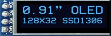
The OLED Display 128x32 is a compact and versatile display module that utilizes organic light-emitting diode (OLED) technology to provide a high-contrast, high-resolution visual output. With a resolution of 128x32 pixels, this display is capable of showing text, graphics, and animations. It is commonly used in consumer electronics, instrumentation panels, and DIY projects, including interfaces with microcontrollers like the Arduino UNO.

Explore Projects Built with oled_display_128_32

Use Cirkit Designer to design, explore, and prototype these projects online. Some projects support real-time simulation. Click "Open Project" to start designing instantly!
ESP32 Devkit V1 and OLED Display Bitmap Viewer
Image of Esp32_monochromeimage: A project utilizing oled_display_128_32 in a practical application
This circuit consists of an ESP32 Devkit V1 microcontroller connected to a 1.3" OLED display via I2C communication. The ESP32 initializes the OLED display and renders a predefined bitmap image on it.
Cirkit Designer LogoOpen Project in Cirkit Designer
Wi-Fi Controlled RGB LED and OLED Display with ESP8266
Image of ESP thermometer reciever: A project utilizing oled_display_128_32 in a practical application
This circuit features an ESP8266 microcontroller interfaced with a 128x64 OLED display via I2C for visual output and an RGB LED controlled through current-limiting resistors. The ESP8266 provides power and control signals to both the display and the LED, enabling visual feedback and status indication.
Cirkit Designer LogoOpen Project in Cirkit Designer
Arduino UNO Controlled OLED Display with 9V Battery and Step-Down Converter
Image of digik: A project utilizing oled_display_128_32 in a practical application
This circuit features an Arduino UNO connected to a 128x64 OLED display via I2C communication lines (SDA and SCL), with the Arduino providing control signals to the display. A 9V battery powers the circuit through a 12v to 5v step-down power converter, which supplies a regulated 5V to both the Arduino and the OLED display. The embedded code on the Arduino is configured to blink an onboard LED with a 1-second interval.
Cirkit Designer LogoOpen Project in Cirkit Designer
ESP32-Controlled Dual 8x8 LED Matrix Display with NTP Time Synchronization
Image of time: A project utilizing oled_display_128_32 in a practical application
This circuit features an ESP32 microcontroller connected to two cascaded 8x8 LED matrix displays, powered by a 3.3V battery. The ESP32 drives the displays to show time and other information, with the code indicating functionality for connecting to WiFi, synchronizing time via NTP, and displaying data on the matrices using custom fonts. Additionally, there is a separate 3.3V battery powering a red LED, which appears to function as a simple indicator light.
Cirkit Designer LogoOpen Project in Cirkit Designer

Explore Projects Built with oled_display_128_32

Use Cirkit Designer to design, explore, and prototype these projects online. Some projects support real-time simulation. Click "Open Project" to start designing instantly!
Image of Esp32_monochromeimage: A project utilizing oled_display_128_32 in a practical application
ESP32 Devkit V1 and OLED Display Bitmap Viewer
This circuit consists of an ESP32 Devkit V1 microcontroller connected to a 1.3" OLED display via I2C communication. The ESP32 initializes the OLED display and renders a predefined bitmap image on it.
Cirkit Designer LogoOpen Project in Cirkit Designer
Image of ESP thermometer reciever: A project utilizing oled_display_128_32 in a practical application
Wi-Fi Controlled RGB LED and OLED Display with ESP8266
This circuit features an ESP8266 microcontroller interfaced with a 128x64 OLED display via I2C for visual output and an RGB LED controlled through current-limiting resistors. The ESP8266 provides power and control signals to both the display and the LED, enabling visual feedback and status indication.
Cirkit Designer LogoOpen Project in Cirkit Designer
Image of digik: A project utilizing oled_display_128_32 in a practical application
Arduino UNO Controlled OLED Display with 9V Battery and Step-Down Converter
This circuit features an Arduino UNO connected to a 128x64 OLED display via I2C communication lines (SDA and SCL), with the Arduino providing control signals to the display. A 9V battery powers the circuit through a 12v to 5v step-down power converter, which supplies a regulated 5V to both the Arduino and the OLED display. The embedded code on the Arduino is configured to blink an onboard LED with a 1-second interval.
Cirkit Designer LogoOpen Project in Cirkit Designer
Image of time: A project utilizing oled_display_128_32 in a practical application
ESP32-Controlled Dual 8x8 LED Matrix Display with NTP Time Synchronization
This circuit features an ESP32 microcontroller connected to two cascaded 8x8 LED matrix displays, powered by a 3.3V battery. The ESP32 drives the displays to show time and other information, with the code indicating functionality for connecting to WiFi, synchronizing time via NTP, and displaying data on the matrices using custom fonts. Additionally, there is a separate 3.3V battery powering a red LED, which appears to function as a simple indicator light.
Cirkit Designer LogoOpen Project in Cirkit Designer

Technical Specifications

Key Technical Details

  • Resolution: 128x32 pixels
  • Color: Monochrome (usually blue or white)
  • Interface: I2C/SPI (depending on the model)
  • Operating Voltage: Typically 3.3V to 5V
  • Current Draw: 10mA to 30mA (varies with brightness and content)
  • Viewing Angle: >160 degrees

Pin Configuration and Descriptions

Pin Number Pin Name Description
1 GND Ground connection
2 VCC Power supply (3.3V - 5V)
3 SCL Serial Clock Line for I2C
4 SDA Serial Data Line for I2C
5 RES Reset pin (optional, depending on model)
6 DC Data/Command control pin (for SPI)
7 CS Chip Select for SPI (optional, depending on model)

Usage Instructions

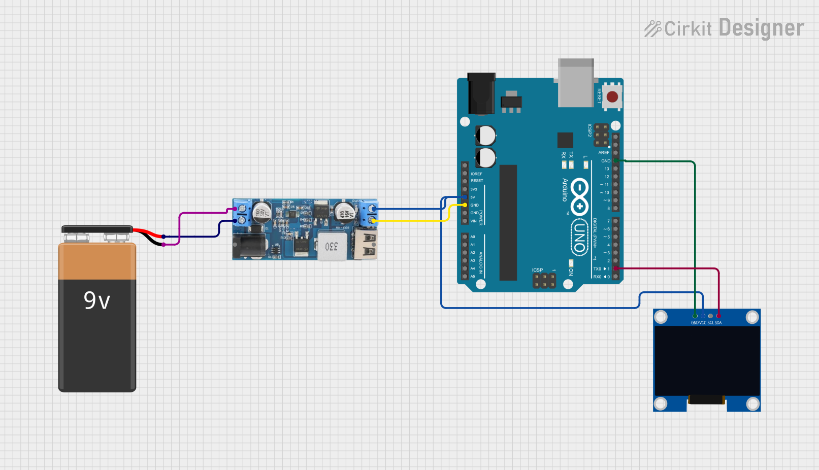
Integration with a Circuit

  1. Power Connections: Connect the VCC pin to a 3.3V or 5V power supply and the GND pin to the ground.
  2. Data Connections: For I2C communication, connect the SCL and SDA pins to the corresponding SCL and SDA pins on the microcontroller. For SPI, connect the DC, CS, and RES pins as required.
  3. Initialization: Upon power-up, the display may require initialization using the microcontroller to start displaying content.

Important Considerations and Best Practices

  • Logic Level: Ensure that the logic level of the microcontroller matches the display's voltage level to prevent damage.
  • Current Limiting: If the display is powered at 5V, consider using a current-limiting resistor to protect the OLED.
  • Library Use: Utilize existing libraries for interfacing with the display to simplify programming.
  • Screen Burn-in: To prevent burn-in, avoid displaying static images for extended periods.

Example Code for Arduino UNO

#include <Wire.h> // Include Wire library for I2C
#include <Adafruit_GFX.h> // Include core graphics library
#include <Adafruit_SSD1306.h> // Include Adafruit_SSD1306 library to control the OLED

// OLED display TWI address (usually 0x3C or 0x3D)
#define OLED_ADDR   0x3C
// Reset pin not used for this display
#define OLED_RESET  -1

// Create an instance of the display
Adafruit_SSD1306 display(128, 32, &Wire, OLED_RESET);

void setup() {
  // Initialize with the I2C addr 0x3C (for the 128x32)
  if(!display.begin(SSD1306_SWITCHCAPVCC, OLED_ADDR)) {
    Serial.println(F("SSD1306 allocation failed"));
    for(;;); // Don't proceed, loop forever
  }
  // Clear the buffer
  display.clearDisplay();
  // Set text size to 1
  display.setTextSize(1);
  // Set text color to white
  display.setTextColor(WHITE);
  // Set cursor position to top-left
  display.setCursor(0,0);
  // Display text
  display.println(F("Hello, OLED!"));
  // Show the display buffer on the screen
  display.display();
}

void loop() {
  // Code to update the display continuously
}

Troubleshooting and FAQs

Common Issues

  • Display Not Turning On: Check the power connections and ensure the correct voltage is applied.
  • Garbled Output: Verify the correct initialization sequence and reset the display if necessary.
  • Dim Display: Adjust the contrast or check if the current draw is within the specified range.

Solutions and Tips for Troubleshooting

  • Check Connections: Loose or incorrect wiring can cause many issues. Double-check all connections.
  • Use Example Code: Start with example code known to work and modify it incrementally.
  • Library Compatibility: Ensure the library version you are using is compatible with your microcontroller and IDE.

FAQs

Q: Can the display show images? A: Yes, the display can show bitmap images that fit within its 128x32 pixel resolution.

Q: Is the display readable in sunlight? A: OLED displays are typically not as visible in direct sunlight as backlit LCDs.

Q: How do I prevent screen burn-in? A: Use screen savers or periodically change the content displayed to prevent burn-in.

Q: Can I use this display with a 5V microcontroller? A: Yes, but ensure that the logic levels are compatible or use a level shifter if necessary.