How to Use TSOP312 IR Receiver: Examples, Pinouts, and Specs

Introduction
The TSOP312 series are miniaturized receivers for infrared remote control systems. A PIN diode and a preamplifier are assembled on a lead frame, the epoxy package acts as an IR filter. The demodulated output signal can be directly connected to a microprocessor for decoding. These components are commonly used in consumer electronics, such as televisions, DVD players, and other devices that can be controlled remotely via IR signals.
Explore Projects Built with TSOP312 IR Receiver
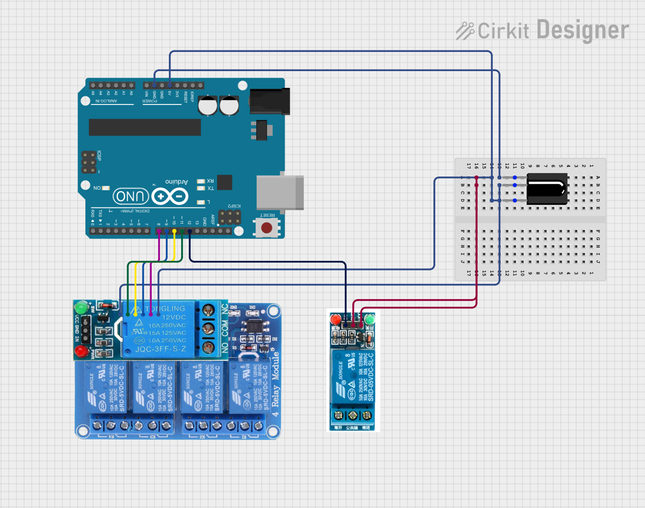
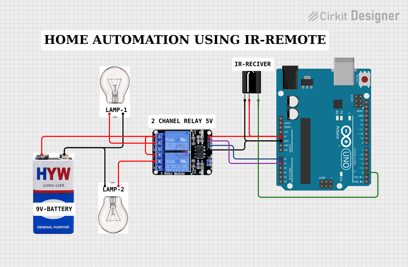
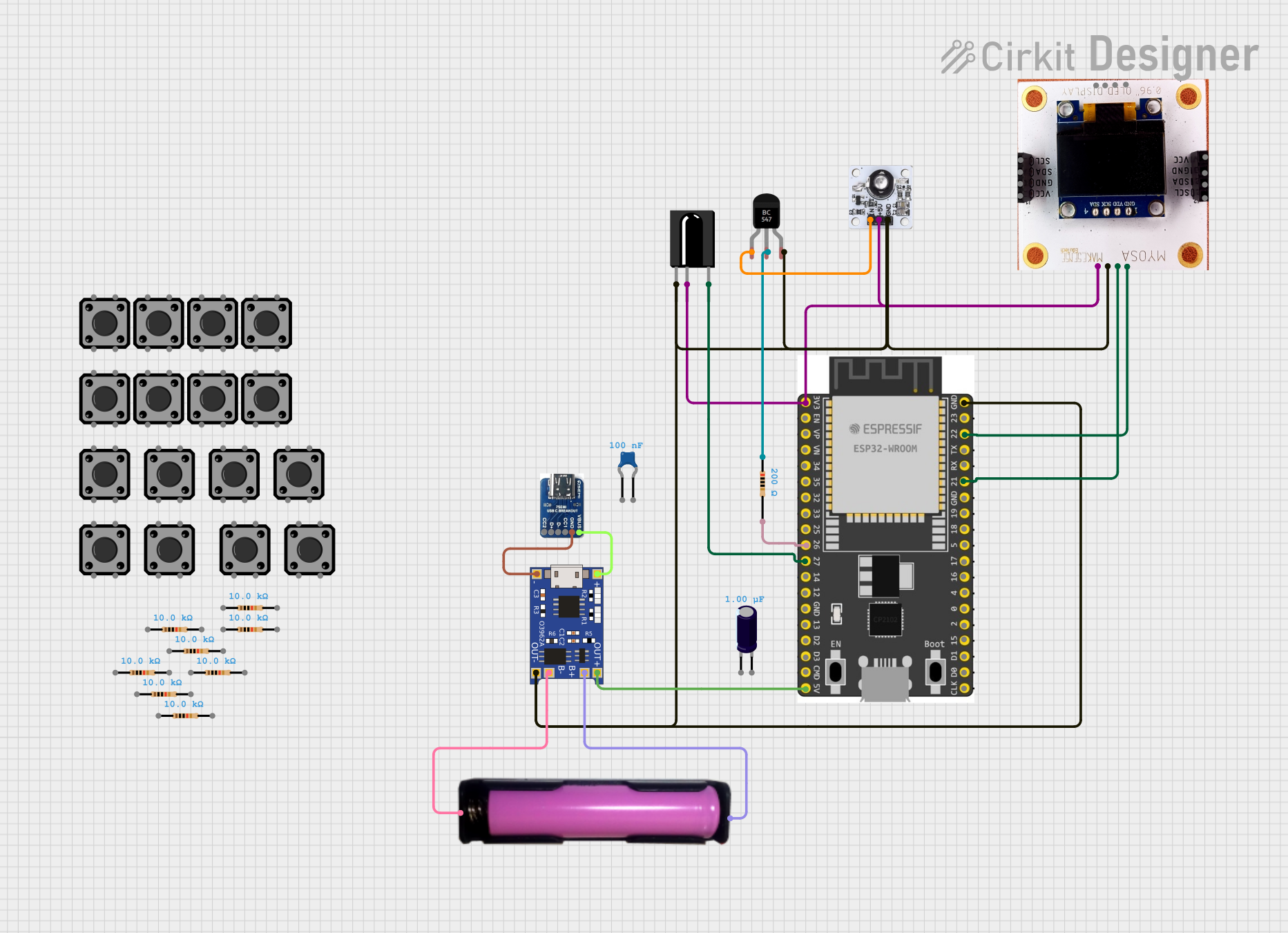
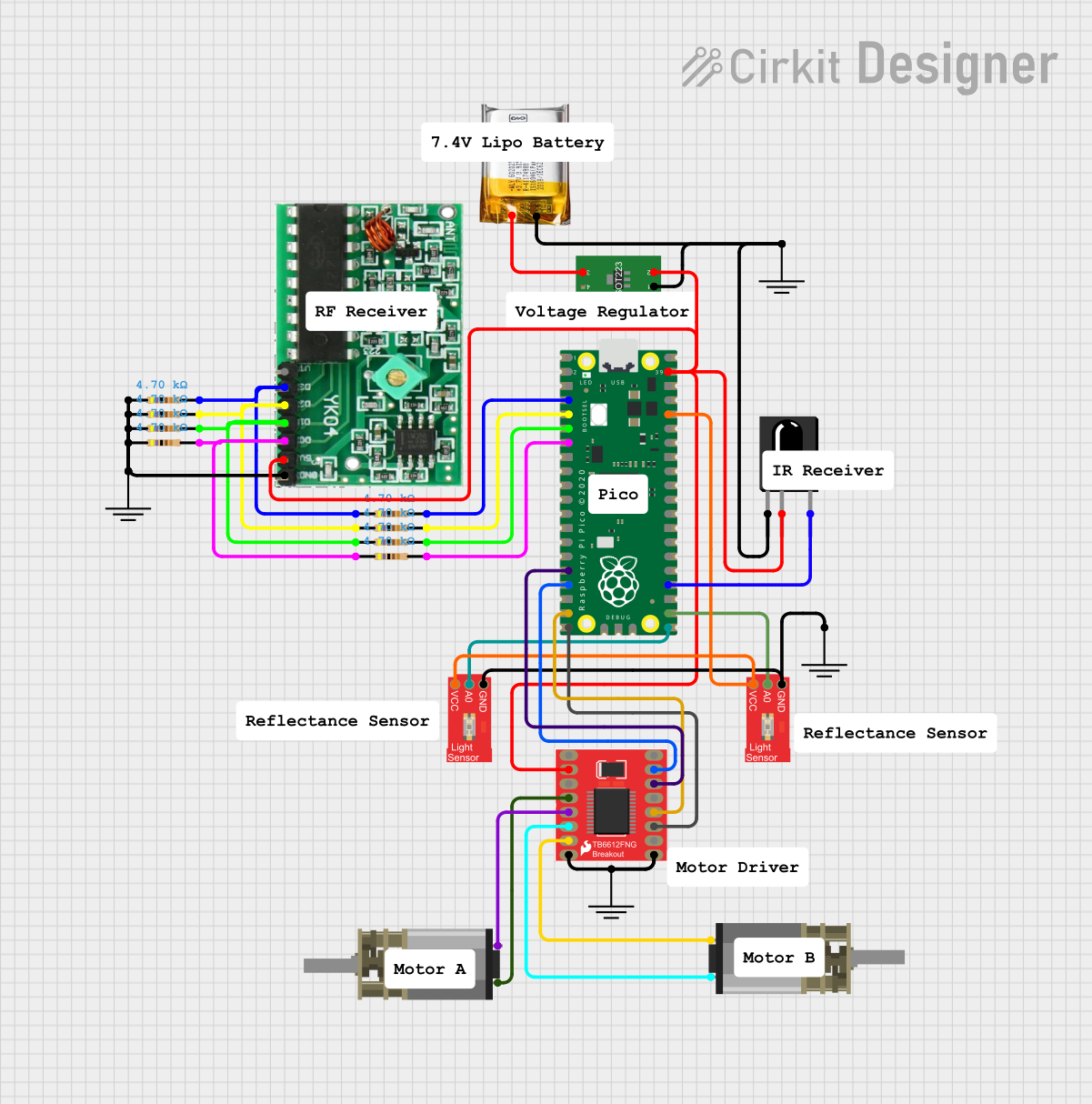
Explore Projects Built with TSOP312 IR Receiver
Common Applications and Use Cases
- Remote control receivers for TVs, audio systems, and air conditioners
- IR-based wireless communication links
- Light barrier systems and touch-less switches
Technical Specifications
Key Technical Details
- Supply Voltage: 2.5V to 5.5V
- Supply Current: 0.4mA to 1.5mA
- Carrier Frequency: 38kHz
- Directivity: 45°
- Operating Temperature: -25°C to +85°C
Pin Configuration and Descriptions
| Pin Number | Name | Description |
|---|---|---|
| 1 | OUT | Output signal (active low) |
| 2 | GND | Ground reference for the circuit |
| 3 | VS | Supply voltage |
Usage Instructions
How to Use the TSOP312 in a Circuit
- Connect the VS pin to a 2.5V to 5.5V power supply.
- Connect the GND pin to the ground of the power supply.
- The OUT pin provides the demodulated IR signal, which should be connected to an interrupt or input pin on a microcontroller for decoding.
Important Considerations and Best Practices
- Ensure that the supply voltage does not exceed the maximum rating of 5.5V.
- Avoid exposure to direct sunlight or other strong IR sources that may interfere with the IR signals.
- Place the TSOP312 away from noise sources such as fluorescent lights and motors.
- Use a series resistor if connecting the OUT pin directly to a microcontroller to limit the current.
Example Arduino UNO Connection and Code
// Connect TSOP312 OUT pin to Arduino pin 2
const int irReceiverPin = 2;

void setup() {
  // Initialize the IR receiver pin as an input
  pinMode(irReceiverPin, INPUT);
  Serial.begin(9600);
}

void loop() {
  // Check if the IR receiver's output is LOW (signal received)
  if (digitalRead(irReceiverPin) == LOW) {
    // Perform an action or decode the signal
    Serial.println("IR signal received");
    delay(100); // Debounce delay
  }
}
Troubleshooting and FAQs
Common Issues
- No Signal Detected: Ensure that the IR emitter is functioning and within the line of sight. Check the connections and supply voltage.
- Intermittent Operation: This could be due to ambient IR light interference. Shield the receiver from unwanted IR sources.
- False Triggers: Noise from electrical sources can cause this. Ensure proper grounding and consider using a filter capacitor close to the VS and GND pins.
Solutions and Tips for Troubleshooting
- Check Connections: Verify that all connections are secure and correct.
- Supply Voltage: Measure the supply voltage to ensure it is within the specified range.
- Ambient Light: Test the receiver in a different location to rule out ambient light interference.
FAQs
Q: Can the TSOP312 be used with any IR remote? A: The TSOP312 is designed to work with 38kHz IR signals, which is a common frequency for many IR remotes.
Q: How can I increase the range of the IR receiver? A: Ensure that there is no obstruction between the transmitter and receiver, and that the receiver is not exposed to strong IR noise sources. Using a higher quality IR emitter can also help.
Q: What should I do if the receiver is too sensitive to ambient light? A: Shield the receiver from direct light sources or use an IR filter to reduce the impact of ambient light.