
How to Use AC voltage sensor: Examples, Pinouts, and Specs
 Design with AC voltage sensor in Cirkit Designer
AC Voltage Sensor Documentation
1. Introduction
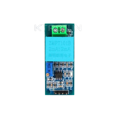
The AC Voltage Sensor is an electronic device designed to measure the voltage of alternating current (AC) in a circuit. It provides real-time data, making it an essential tool for monitoring and control applications. This sensor is widely used in various fields, including industrial automation, home energy monitoring, and power system analysis. By converting high AC voltages into a measurable signal, the sensor ensures safe and accurate voltage readings.
Common Applications:
- Energy Monitoring Systems: Track power consumption in residential, commercial, and industrial setups.
- Power Quality Analysis: Measure and analyze voltage fluctuations in power systems.
- Automation Systems: Monitor voltage levels in automated machinery and equipment.
- Educational Projects: Learn about AC voltage measurement in electronics and IoT projects.
2. Technical Specifications
The following table outlines the key technical details of a typical AC Voltage Sensor:
| Parameter | Value |
|---|---|
| Input Voltage Range | 0–250V AC |
| Output Voltage Range | 0–5V DC (proportional to input) |
| Accuracy | ±1% |
| Operating Voltage | 5V DC |
| Operating Current | ≤10mA |
| Isolation Voltage | 2000V (galvanic isolation) |
| Response Time | ≤200ms |
| Operating Temperature | -40°C to +85°C |
| Dimensions | 50mm x 25mm x 20mm |
Pin Configuration and Descriptions
| Pin | Name | Description |
|---|---|---|
| 1 | VCC | Power supply input (5V DC). Connect to the 5V pin of your microcontroller. |
| 2 | GND | Ground connection. Connect to the GND pin of your microcontroller. |
| 3 | Signal (OUT) | Analog output signal proportional to the AC voltage being measured. |
| 4 | AC Input (L) | Live wire input for the AC voltage to be measured. |
| 5 | AC Input (N) | Neutral wire input for the AC voltage to be measured. |
3. Usage Instructions
How to Use the AC Voltage Sensor in a Circuit:
- Power the Sensor: Connect the
VCCpin to a 5V DC power source and theGNDpin to ground. - Connect the AC Input: Attach the live (L) and neutral (N) wires of the AC circuit to the respective input terminals of the sensor. Ensure proper insulation and safety precautions.
- Read the Output Signal: The
Signal (OUT)pin provides an analog voltage proportional to the AC voltage being measured. Connect this pin to the analog input of a microcontroller (e.g., Arduino). - Calibrate the Sensor: Use a known AC voltage source to calibrate the sensor and map the output voltage to the actual AC voltage.
Important Considerations:
- Safety First: Always handle AC voltage with care. Ensure proper insulation and avoid direct contact with live wires.
- Isolation: The sensor provides galvanic isolation, but additional isolation (e.g., optocouplers) may be required for high-voltage applications.
- Filtering: Use capacitors or software-based filtering to smooth out noise in the output signal.
- Calibration: The sensor's output is proportional to the input voltage but may require calibration for precise measurements.
4. Example Arduino Code
Below is an example of how to use the AC Voltage Sensor with an Arduino UNO to measure and display the AC voltage on the Serial Monitor.
// AC Voltage Sensor Example Code
// This code reads the analog output of the AC Voltage Sensor and calculates
// the corresponding AC voltage. Ensure proper calibration for accurate results.

const int sensorPin = A0;  // Analog pin connected to the sensor's Signal (OUT)
const float calibrationFactor = 250.0 / 1023.0;
// Calibration factor: 250V max input mapped to 0-1023 ADC range

void setup() {
  Serial.begin(9600);  // Initialize serial communication at 9600 baud
}

void loop() {
  int sensorValue = analogRead(sensorPin);  // Read the analog value from the sensor
  float voltage = sensorValue * calibrationFactor;
  // Convert the ADC value to AC voltage using the calibration factor

  Serial.print("AC Voltage: ");
  Serial.print(voltage);
  Serial.println(" V");  // Print the voltage value to the Serial Monitor

  delay(500);  // Wait for 500ms before the next reading
}
Notes:
- Replace the
calibrationFactorwith the actual value determined during calibration. - Ensure the sensor is properly connected to the Arduino and the AC circuit.
5. Troubleshooting and FAQs
Common Issues and Solutions:
| Issue | Possible Cause | Solution |
|---|---|---|
| No output signal | Incorrect wiring or loose connections | Double-check all connections, especially VCC, GND, and Signal (OUT). |
| Inaccurate voltage readings | Calibration not performed | Calibrate the sensor using a known AC voltage source. |
| Fluctuating or noisy output | Electrical noise or interference | Add a capacitor (e.g., 0.1µF) across the output to filter noise. |
| Sensor overheating | Exceeding input voltage range | Ensure the input voltage does not exceed the sensor's rated range (250V AC). |
| Arduino not detecting the sensor output | Faulty analog pin or incorrect code | Verify the Arduino code and test the analog pin with a known voltage source. |
Frequently Asked Questions (FAQs):
Can this sensor measure DC voltage?
- No, this sensor is specifically designed for AC voltage measurement.
What is the maximum AC voltage it can measure?
- The sensor can measure up to 250V AC. Exceeding this limit may damage the sensor.
How do I ensure safety while using this sensor?
- Use proper insulation, avoid direct contact with live wires, and follow standard electrical safety practices.
Can I use this sensor with a 3.3V microcontroller?
- Yes, but ensure the output signal is within the ADC range of the microcontroller. You may need to adjust the calibration factor.
Why is the output signal not linear?
- The sensor's output is generally linear, but inaccuracies may arise due to improper calibration or noise. Ensure proper calibration and filtering.
This documentation provides a comprehensive guide to understanding, using, and troubleshooting the AC Voltage Sensor. By following the instructions and best practices outlined here, users can safely and effectively integrate this sensor into their projects.
Explore Projects Built with AC voltage sensor
 Open Project in Cirkit Designer
 Open Project in Cirkit Designer
 Open Project in Cirkit Designer
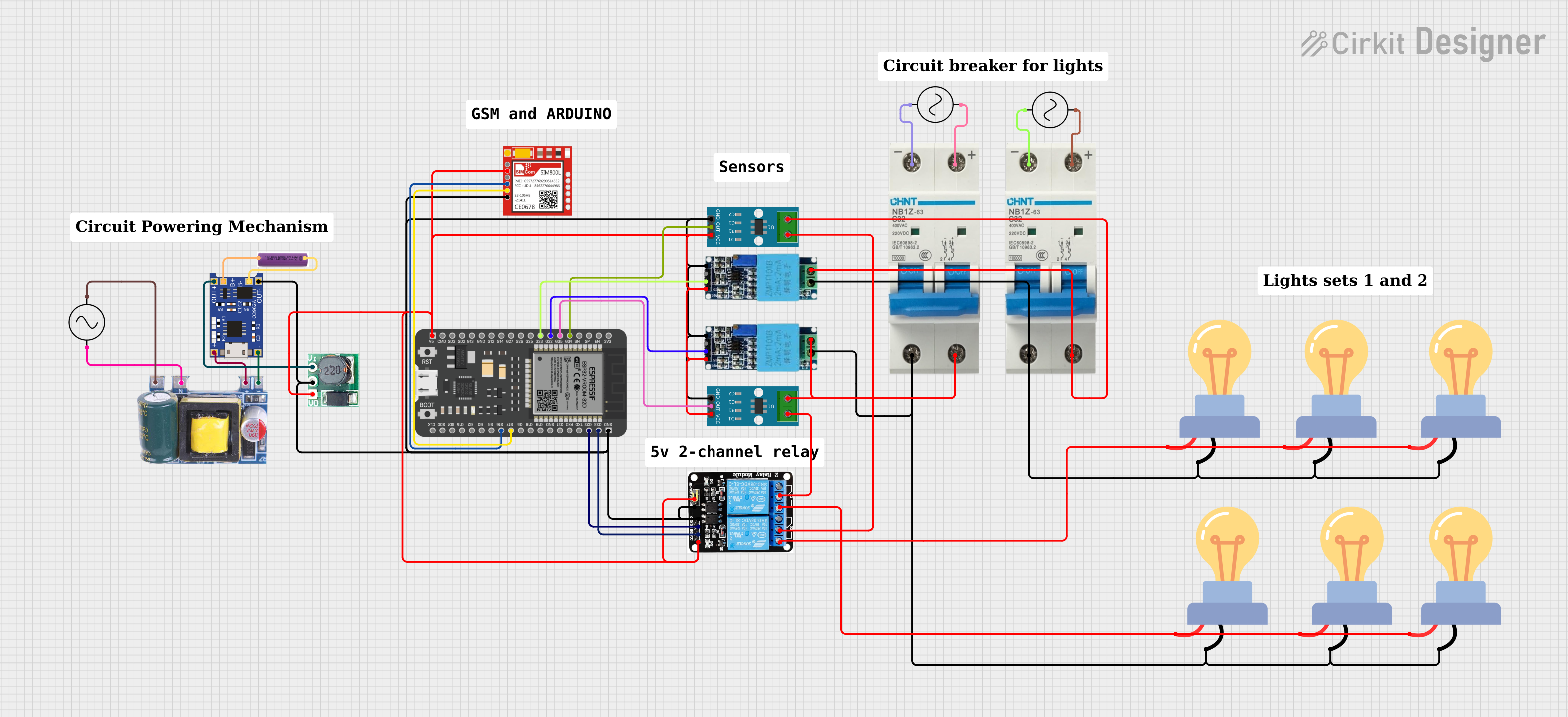 Open Project in Cirkit Designer
Explore Projects Built with AC voltage sensor
Open Project in Cirkit DesignerOpen Project in Cirkit DesignerOpen Project in Cirkit DesignerOpen Project in Cirkit Designer