
How to Use MAX7456: Examples, Pinouts, and Specs

 Design with MAX7456 in Cirkit Designer
Introduction
The MAX7456 is a monochrome on-screen display (OSD) generator designed to overlay text and graphics onto video signals. It simplifies the process of adding custom information, such as telemetry data, to video feeds. The device is widely used in applications like video cameras, drones, security systems, and other video-based systems requiring real-time data display.
The MAX7456 supports NTSC and PAL video standards, making it versatile for global applications. It features an internal character memory and allows users to customize the character set for specific needs. Its SPI interface ensures easy integration with microcontrollers and other digital systems.
Explore Projects Built with MAX7456
 Open Project in Cirkit Designer
 Open Project in Cirkit Designer
 Open Project in Cirkit Designer
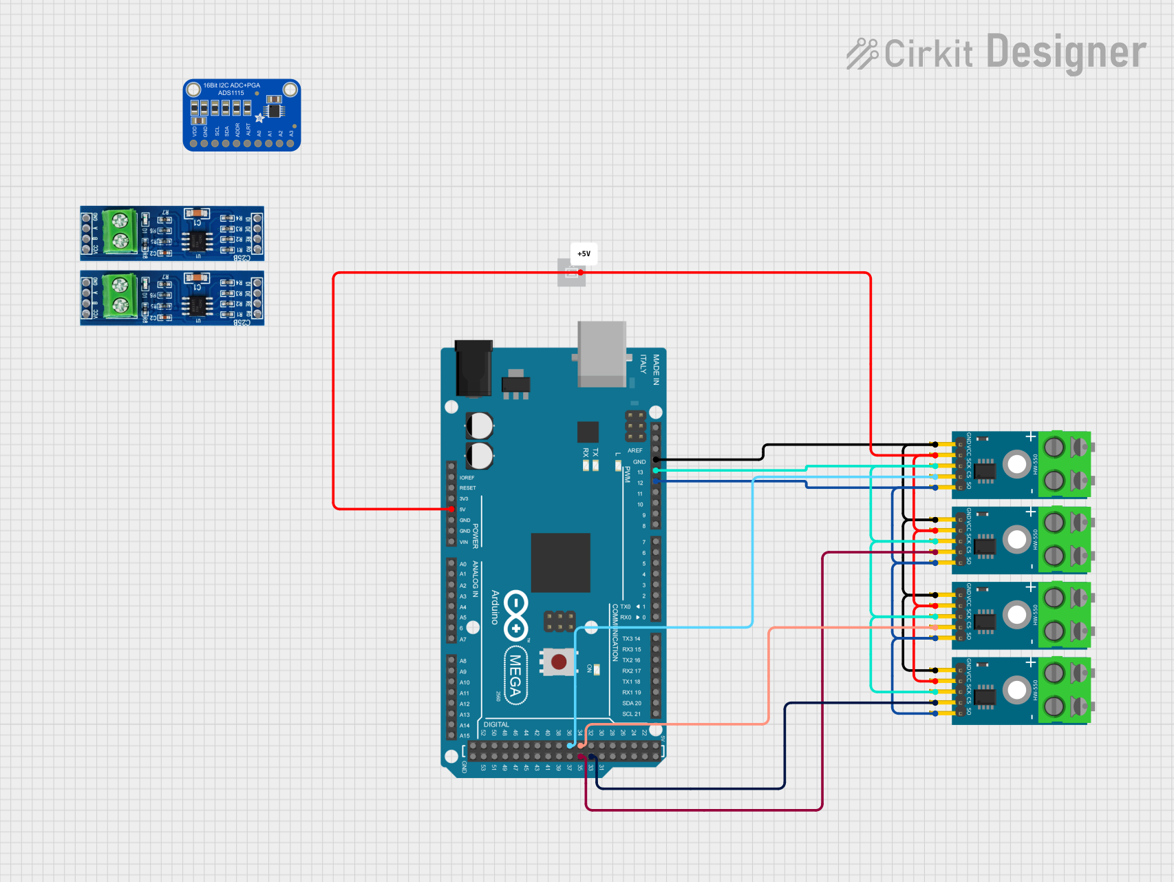 Open Project in Cirkit Designer
Explore Projects Built with MAX7456
Open Project in Cirkit DesignerOpen Project in Cirkit DesignerOpen Project in Cirkit DesignerOpen Project in Cirkit DesignerTechnical Specifications
Below are the key technical details of the MAX7456:
- Supply Voltage (VCC): 4.75V to 5.25V
- Operating Current: 50mA (typical)
- Video Standards Supported: NTSC and PAL
- Character Memory: 256 user-programmable characters
- Interface: SPI (Serial Peripheral Interface)
- Operating Temperature Range: -20°C to +70°C
- Package Type: 28-pin PDIP, SO, or TSSOP
Pin Configuration and Descriptions
The MAX7456 has 28 pins. The table below describes the pin functions:
| Pin Number | Pin Name | Description |
|---|---|---|
| 1 | GND | Ground connection. |
| 2 | VCC | Power supply input (4.75V to 5.25V). |
| 3 | CS | Chip Select for SPI communication. Active low. |
| 4 | SCLK | SPI clock input. |
| 5 | MOSI | SPI Master Out Slave In (data input). |
| 6 | MISO | SPI Master In Slave Out (data output). |
| 7 | RESET | Active-low reset input. |
| 8 | VIDEO_IN | Composite video input. |
| 9 | VIDEO_OUT | Composite video output with OSD overlay. |
| 10 | GND | Ground connection. |
| 11-28 | NC | No connection (reserved for internal use). |
Usage Instructions
How to Use the MAX7456 in a Circuit
- Power Supply: Connect the VCC pin to a regulated 5V power supply and GND to ground.
- Video Signal: Feed the composite video signal into the VIDEO_IN pin. The processed video with OSD overlay will be available at the VIDEO_OUT pin.
- SPI Communication: Use the SPI interface (CS, SCLK, MOSI, MISO) to configure the MAX7456 and send character data. Ensure the microcontroller's SPI settings match the MAX7456 requirements.
- Character Set Programming: The MAX7456 comes with a default character set, but you can program custom characters into its internal memory via SPI.
- Reset: Use the RESET pin to initialize the device during startup or after a fault.
Important Considerations and Best Practices
- Video Signal Compatibility: Ensure the input video signal matches the NTSC or PAL standard.
- Decoupling Capacitors: Place decoupling capacitors (e.g., 0.1µF) near the VCC pin to reduce noise.
- SPI Timing: Follow the SPI timing requirements specified in the MAX7456 datasheet to avoid communication errors.
- Heat Management: Operate the device within the recommended temperature range to prevent overheating.
- Character Memory: Back up custom character sets externally, as reprogramming may be required after a power cycle.
Example: Connecting MAX7456 to Arduino UNO
Below is an example of how to connect and program the MAX7456 with an Arduino UNO to display text on a video signal.
Wiring Diagram
- MAX7456 Pin CS → Arduino Pin 10
- MAX7456 Pin SCLK → Arduino Pin 13
- MAX7456 Pin MOSI → Arduino Pin 11
- MAX7456 Pin MISO → Arduino Pin 12
- MAX7456 Pin VIDEO_IN → Composite video source
- MAX7456 Pin VIDEO_OUT → Composite video display
- MAX7456 Pin VCC → 5V
- MAX7456 Pin GND → GND
Arduino Code Example
#include <SPI.h>

// Define MAX7456 pins
const int MAX7456_CS = 10; // Chip Select pin

void setup() {
  // Initialize SPI
  SPI.begin();
  pinMode(MAX7456_CS, OUTPUT);
  digitalWrite(MAX7456_CS, HIGH); // Set CS high to disable MAX7456

  // Initialize MAX7456
  initializeMAX7456();
}

void loop() {
  // Example: Display "Hello" on the screen
  displayText("Hello");
}

void initializeMAX7456() {
  digitalWrite(MAX7456_CS, LOW); // Select MAX7456
  SPI.transfer(0x00); // Example: Send initialization command
  SPI.transfer(0x01); // Example: Send data
  digitalWrite(MAX7456_CS, HIGH); // Deselect MAX7456
}

void displayText(const char* text) {
  digitalWrite(MAX7456_CS, LOW); // Select MAX7456
  for (int i = 0; text[i] != '\0'; i++) {
    SPI.transfer(text[i]); // Send each character
  }
  digitalWrite(MAX7456_CS, HIGH); // Deselect MAX7456
}
Troubleshooting and FAQs
Common Issues
No OSD Output:
- Cause: Incorrect wiring or missing video input.
- Solution: Verify all connections, especially VIDEO_IN and VIDEO_OUT. Ensure the video source is active.
SPI Communication Fails:
- Cause: Mismatched SPI settings or incorrect wiring.
- Solution: Check the SPI clock speed and mode. Ensure CS, SCLK, MOSI, and MISO are correctly connected.
Custom Characters Not Displaying:
- Cause: Character memory not programmed or corrupted.
- Solution: Reprogram the character memory via SPI.
Device Overheating:
- Cause: Operating outside the recommended temperature range.
- Solution: Ensure proper ventilation and operate within -20°C to +70°C.
FAQs
Q: Can the MAX7456 work with HDMI signals?
A: No, the MAX7456 is designed for composite video signals (NTSC/PAL). Use an HDMI-to-composite converter if needed.
Q: How many characters can the MAX7456 display at once?
A: The MAX7456 can display up to 16 rows by 30 columns of characters, depending on the video standard.
Q: Is the MAX7456 compatible with 3.3V microcontrollers?
A: The MAX7456 requires 5V for operation. Use level shifters to interface with 3.3V microcontrollers.
Q: Can I use the MAX7456 without programming custom characters?
A: Yes, the MAX7456 includes a default character set that can be used without additional programming.