How to Use esc: Examples, Pinouts, and Specs
Introduction
An Electronic Speed Controller (ESC) is a critical component used to regulate the speed, direction, and braking of electric motors. It is commonly found in remote-controlled vehicles, drones, and other applications requiring precise motor control. By adjusting the power supplied to the motor based on input signals, the ESC ensures smooth and efficient operation.
Explore Projects Built with esc

Explore Projects Built with esc
Common Applications and Use Cases
- Remote-controlled cars, boats, and airplanes
- Drones and quadcopters
- Electric bicycles and scooters
- Robotics and automation systems
- Industrial motor control applications
Technical Specifications
Below are the general technical specifications for an ESC. Note that specific values may vary depending on the manufacturer and model.
Key Technical Details
- Input Voltage Range: 6V to 50V (varies by model)
- Current Rating: 10A to 200A (continuous, depending on the ESC)
- Supported Motor Types: Brushless DC (BLDC) or Brushed DC motors
- Signal Input: Pulse Width Modulation (PWM) signal (typically 1ms to 2ms pulse width)
- BEC (Battery Eliminator Circuit): 5V or 6V output for powering external devices (optional, depending on model)
- Thermal Protection: Over-temperature shutdown
- Safety Features: Overcurrent protection, low-voltage cutoff, and fail-safe modes
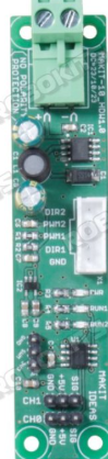
Pin Configuration and Descriptions
The ESC typically has three main sets of connections: motor wires, power input, and signal input. Below is a table describing these connections.
| Pin/Connection | Description |
|---|---|
| Motor Wires (A, B, C) | Connect to the three-phase terminals of a brushless motor. |
| Power Input (+, -) | Connect to the battery or power source. Ensure correct polarity. |
| Signal Input (PWM) | Receives control signals from a receiver or microcontroller (e.g., Arduino). |
| BEC Output (optional) | Provides regulated 5V or 6V power for external devices like a receiver. |
Usage Instructions
How to Use the ESC in a Circuit
- Connect the Motor: Attach the three motor wires (A, B, C) from the ESC to the corresponding terminals on the brushless motor. The order of connection determines the motor's rotation direction. Swap any two wires to reverse the direction.
- Connect the Power Source: Attach the positive (+) and negative (-) terminals of the ESC to the battery or power source. Double-check the voltage and polarity to avoid damage.
- Connect the Signal Input: Use a PWM signal from a receiver or microcontroller (e.g., Arduino) to control the ESC. The signal wire is typically white or yellow, while the ground wire is black or brown.
- Optional BEC Connection: If the ESC has a built-in BEC, use the output to power external devices like a receiver or microcontroller.
Important Considerations and Best Practices
- Voltage and Current Ratings: Ensure the ESC's voltage and current ratings match the motor and power source requirements.
- Cooling: Provide adequate cooling for high-power ESCs to prevent overheating.
- Calibration: Some ESCs require calibration to match the PWM signal range of the controller.
- Startup Safety: Always ensure the motor is stationary and the throttle is at zero before powering on the ESC.
- Firmware Updates: Check if the ESC supports firmware updates for improved performance and features.
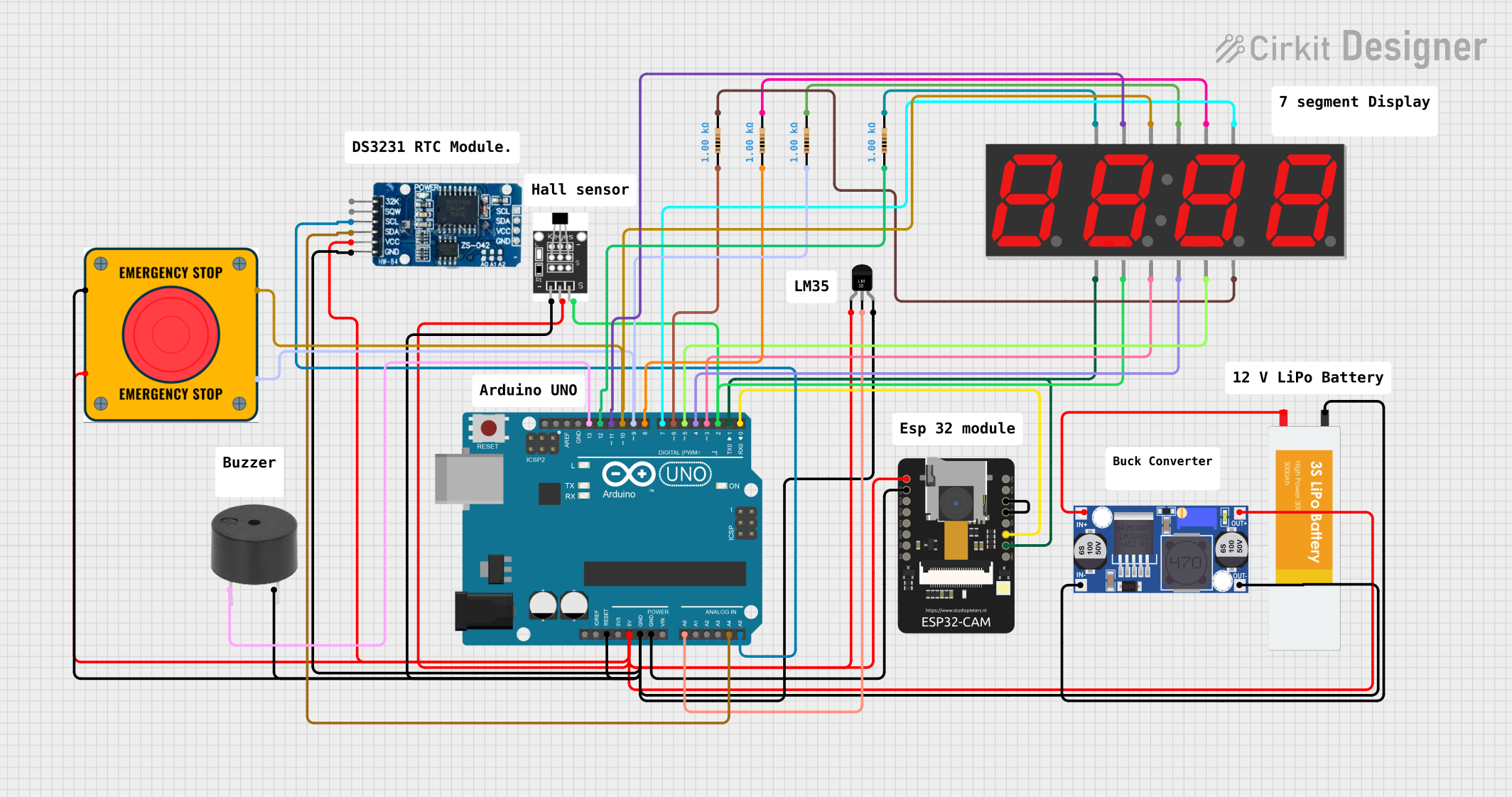
Example: Using an ESC with Arduino UNO
Below is an example of how to control an ESC using an Arduino UNO. This code generates a PWM signal to adjust the motor speed.
#include <Servo.h> // Include the Servo library to generate PWM signals

Servo esc; // Create a Servo object to control the ESC

void setup() {
  esc.attach(9); // Attach the ESC signal wire to pin 9 on the Arduino
  esc.writeMicroseconds(1000); // Set the ESC to minimum throttle (1000 µs)
  delay(2000); // Wait for 2 seconds to allow the ESC to initialize
}

void loop() {
  esc.writeMicroseconds(1500); // Set throttle to 50% (1500 µs)
  delay(5000); // Run the motor at 50% speed for 5 seconds

  esc.writeMicroseconds(2000); // Set throttle to 100% (2000 µs)
  delay(5000); // Run the motor at full speed for 5 seconds

  esc.writeMicroseconds(1000); // Set throttle to 0% (1000 µs)
  delay(5000); // Stop the motor for 5 seconds
}
Troubleshooting and FAQs
Common Issues and Solutions
Motor Does Not Spin
- Cause: Incorrect wiring or no signal input.
- Solution: Verify motor and power connections. Ensure the PWM signal is being sent to the ESC.
Motor Spins in the Wrong Direction
- Cause: Incorrect motor wire connections.
- Solution: Swap any two motor wires to reverse the direction.
ESC Overheats
- Cause: Insufficient cooling or excessive current draw.
- Solution: Add a heatsink or cooling fan. Ensure the motor and ESC are within their rated specifications.
ESC Does Not Initialize
- Cause: Throttle not set to minimum during startup.
- Solution: Ensure the PWM signal is set to the minimum throttle value (e.g., 1000 µs).
Motor Stutters or Jerks
- Cause: Poor connections or incompatible motor.
- Solution: Check all connections and ensure the motor is compatible with the ESC.
FAQs
Q: Can I use an ESC with a brushed motor?
A: Only if the ESC is specifically designed for brushed motors. Most ESCs are for brushless motors.Q: What is the purpose of the BEC?
A: The BEC provides regulated power (5V or 6V) to external devices, eliminating the need for a separate power source.Q: How do I calibrate my ESC?
A: Refer to the ESC's user manual. Typically, you set the throttle to maximum, power on the ESC, then set the throttle to minimum.Q: Can I use an ESC with a higher voltage battery?
A: Only if the ESC's voltage rating supports the battery voltage. Exceeding the rating can damage the ESC.
By following this documentation, you can effectively use and troubleshoot an ESC in your projects.