
How to Use Serial Bus Servo Driver: Examples, Pinouts, and Specs
 Design with Serial Bus Servo Driver in Cirkit Designer
Introduction
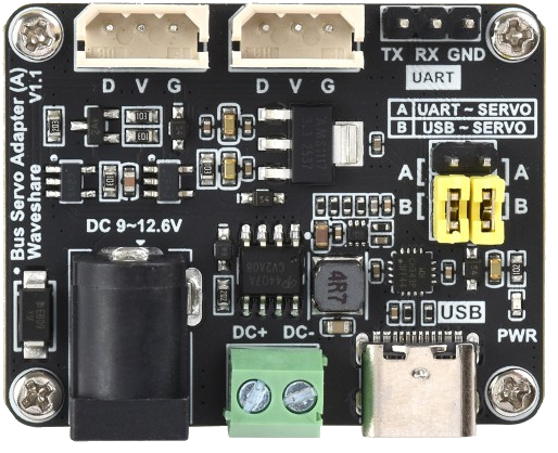
The Serial Bus Servo Driver (Manufacturer Part ID: 25514 / Bus Servo Adapter (A)) by Waveshare is a versatile device designed to control multiple servo motors over a single communication line. This component simplifies the management of servo motors in robotics and automation applications by enabling efficient communication and control. It is particularly useful in scenarios where space and wiring complexity need to be minimized.
Explore Projects Built with Serial Bus Servo Driver
 Open Project in Cirkit Designer
 Open Project in Cirkit Designer
 Open Project in Cirkit Designer
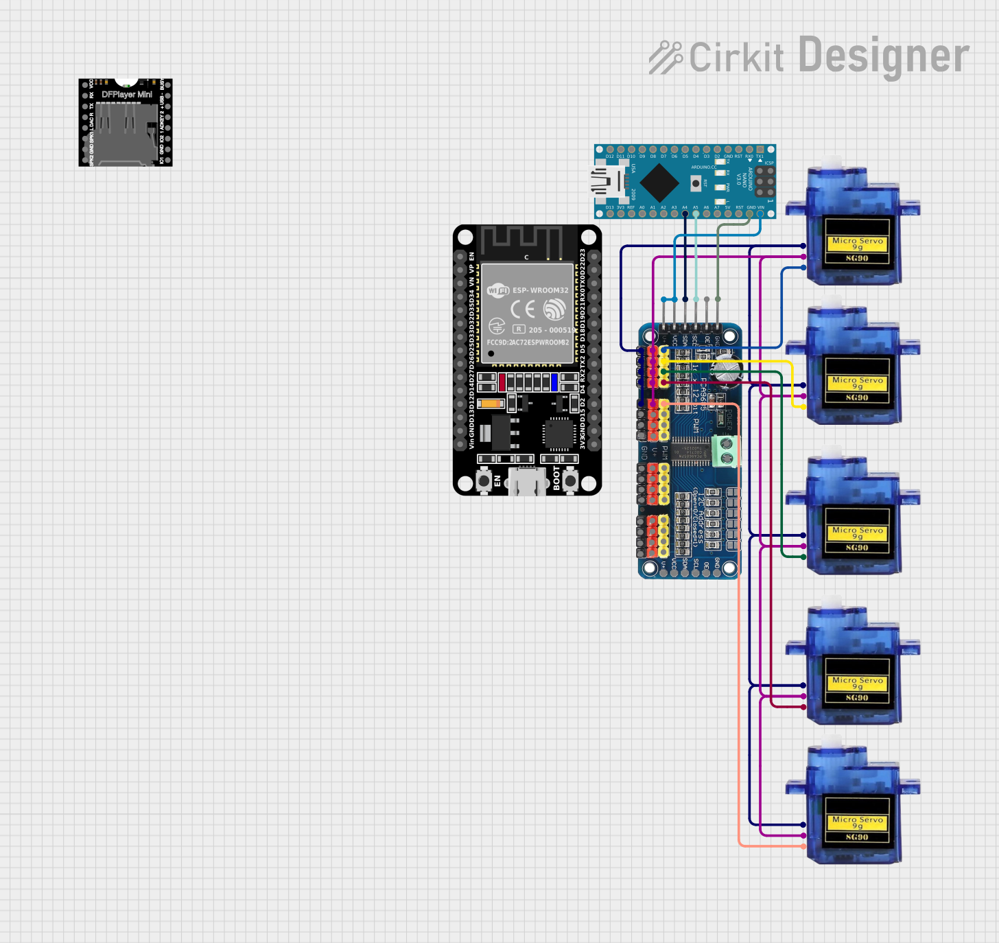 Open Project in Cirkit Designer
Explore Projects Built with Serial Bus Servo Driver
Open Project in Cirkit DesignerOpen Project in Cirkit DesignerOpen Project in Cirkit DesignerOpen Project in Cirkit DesignerCommon Applications and Use Cases
- Robotics: Controlling multiple servo motors in robotic arms, humanoid robots, and mobile robots.
- Automation: Managing servo motors in conveyor systems, pick-and-place machines, and other automated systems.
- Educational Projects: Simplifying servo control for students and hobbyists working on Arduino or Raspberry Pi projects.
- Animatronics: Coordinating servo movements for lifelike animations.
Technical Specifications
The following table outlines the key technical details of the Serial Bus Servo Driver:
| Parameter | Specification |
|---|---|
| Operating Voltage | 5V DC |
| Communication Protocol | UART (Serial Communication) |
| Baud Rate | Configurable (default: 115200 bps) |
| Servo Compatibility | Supports TTL serial bus servos |
| Number of Servos | Up to 253 servos on a single bus |
| Control Modes | Position, speed, and torque control |
| Dimensions | 40mm x 30mm x 10mm |
| Operating Temperature | -20°C to 85°C |
Pin Configuration and Descriptions
The Serial Bus Servo Driver features the following pin layout:
| Pin Name | Description |
|---|---|
| VCC | Power input (5V DC) |
| GND | Ground |
| TX | UART transmit pin (connect to RX of the controller) |
| RX | UART receive pin (connect to TX of the controller) |
| BUS+ | Positive terminal for the servo bus |
| BUS- | Negative terminal for the servo bus |
Usage Instructions
How to Use the Component in a Circuit
- Power Supply: Connect the VCC and GND pins to a stable 5V DC power source. Ensure the power supply can handle the current requirements of all connected servos.
- UART Connection: Connect the TX pin of the Serial Bus Servo Driver to the RX pin of your microcontroller (e.g., Arduino UNO). Similarly, connect the RX pin of the driver to the TX pin of the microcontroller.
- Servo Bus: Connect the BUS+ and BUS- terminals to the corresponding terminals of the TTL serial bus servos.
- Programming: Use the UART interface to send commands to the Serial Bus Servo Driver. Commands can control servo position, speed, and torque.
Important Considerations and Best Practices
- Power Supply: Ensure the power supply is capable of providing sufficient current for all connected servos. Undervoltage or insufficient current can cause erratic servo behavior.
- Baud Rate: Configure the baud rate of the microcontroller to match the baud rate of the Serial Bus Servo Driver (default: 115200 bps).
- Wiring: Keep the wiring as short as possible to minimize signal degradation, especially when controlling multiple servos.
- Initialization: Always initialize the servos to a known position before starting operations to avoid unexpected movements.
Example Code for Arduino UNO
Below is an example Arduino sketch to control a servo using the Serial Bus Servo Driver:
#include <SoftwareSerial.h>

// Define RX and TX pins for SoftwareSerial
#define RX_PIN 10  // Connect to TX of the Serial Bus Servo Driver
#define TX_PIN 11  // Connect to RX of the Serial Bus Servo Driver

SoftwareSerial servoSerial(RX_PIN, TX_PIN);

void setup() {
  servoSerial.begin(115200); // Initialize UART communication at 115200 bps
  delay(100); // Allow time for the Serial Bus Servo Driver to initialize

  // Example command to set servo ID 1 to position 500 (range: 0-1000)
  sendServoCommand(1, 500);
}

void loop() {
  // Add your main code here
}

// Function to send a command to the servo
void sendServoCommand(uint8_t servoID, uint16_t position) {
  uint8_t command[6];
  command[0] = 0x55; // Header byte 1
  command[1] = 0x55; // Header byte 2
  command[2] = servoID; // Servo ID
  command[3] = 3; // Length of the command
  command[4] = 1; // Command type: Move to position
  command[5] = position & 0xFF; // Position low byte
  command[6] = (position >> 8) & 0xFF; // Position high byte

  // Send the command over UART
  for (uint8_t i = 0; i < 7; i++) {
    servoSerial.write(command[i]);
  }
}
Troubleshooting and FAQs
Common Issues and Solutions
Servos Not Responding
- Cause: Incorrect wiring or baud rate mismatch.
- Solution: Double-check the wiring and ensure the baud rate of the microcontroller matches the Serial Bus Servo Driver.
Erratic Servo Movements
- Cause: Insufficient power supply or electrical noise.
- Solution: Use a power supply with adequate current capacity and add decoupling capacitors to reduce noise.
Communication Errors
- Cause: Long or poor-quality wires causing signal degradation.
- Solution: Use shorter, high-quality wires and ensure proper grounding.
Overheating
- Cause: Excessive load on the servos or prolonged operation at high torque.
- Solution: Reduce the load on the servos and allow them to cool periodically.
FAQs
Can I use this driver with analog servos?
- No, the Serial Bus Servo Driver is designed specifically for TTL serial bus servos.
What is the maximum cable length for the servo bus?
- The maximum cable length depends on the quality of the wires and the operating environment. For best results, keep the cable length under 1 meter.
How do I change the baud rate of the driver?
- Refer to the manufacturer's documentation for instructions on configuring the baud rate.
Can I control servos with different IDs simultaneously?
- Yes, you can send commands to multiple servos by specifying their unique IDs in the command.
This documentation provides a comprehensive guide to using the Waveshare Serial Bus Servo Driver effectively. For further details, refer to the manufacturer's datasheet or support resources.