Cirkit Designer Logo
Cirkit Designer
Your all-in-one circuit design IDE
Home / 
Component Documentation

How to Use DC-DC Step-up Boost Converter - 2A - 5V Output: Examples, Pinouts, and Specs

Image of DC-DC Step-up Boost Converter - 2A - 5V Output
Cirkit Designer LogoDesign with DC-DC Step-up Boost Converter - 2A - 5V Output in Cirkit Designer

Introduction

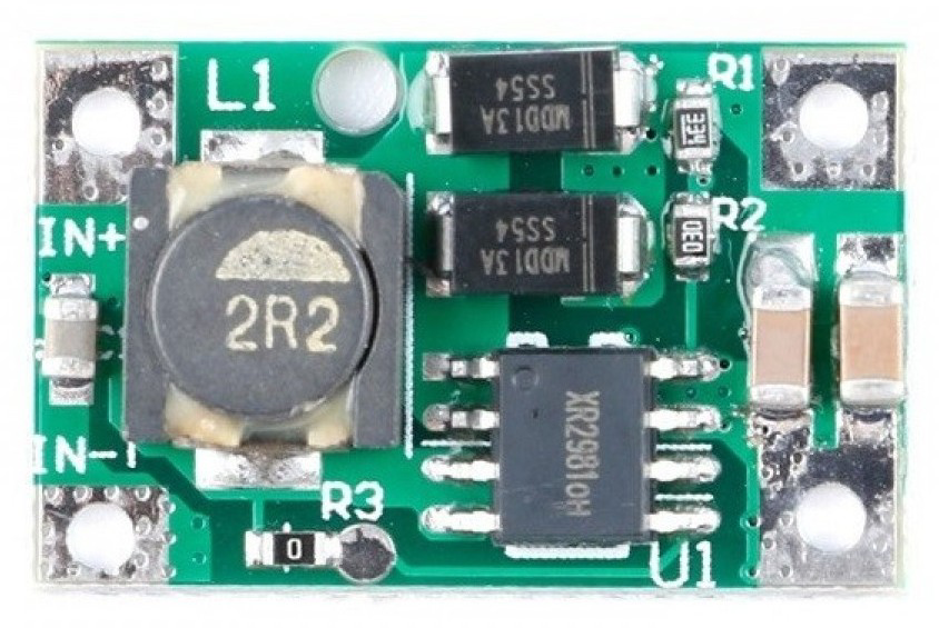
The DC-DC Step-up Boost Converter - 2A - 5V Output by TinyTronics is a compact and efficient power management module designed to increase a lower input voltage to a stable 5V output. This boost converter is capable of delivering up to 2A of current, making it ideal for powering USB devices, microcontrollers, and other 5V electronics from lower voltage sources such as batteries.

Explore Projects Built with DC-DC Step-up Boost Converter - 2A - 5V Output

Use Cirkit Designer to design, explore, and prototype these projects online. Some projects support real-time simulation. Click "Open Project" to start designing instantly!
Battery-Powered Lora G2 Node Station with 18650 Li-ion Batteries and Boost Converter
Image of Custom-Lora-G2-Node: A project utilizing DC-DC Step-up Boost Converter - 2A - 5V Output in a practical application
This circuit is a portable power supply system that uses multiple 18650 Li-ion batteries to provide a stable 5V output through a boost converter. It includes a fast charging module with a USB-C input for recharging the batteries and a battery indicator for monitoring the battery status. The system powers a Lora G2 Node Station, making it suitable for wireless communication applications.
Cirkit Designer LogoOpen Project in Cirkit Designer
DC-DC Converter and Relay Module Power Distribution System
Image of relay: A project utilizing DC-DC Step-up Boost Converter - 2A - 5V Output in a practical application
This circuit consists of a DC-DC converter powering a 6-channel power module, which in turn supplies 5V to a 2-relay module. The power module distributes the converted voltage to the relay module, enabling it to control external devices.
Cirkit Designer LogoOpen Project in Cirkit Designer
Multi-Stage Voltage Regulation and Indicator LED Circuit
Image of Subramanyak_Power_Circuit: A project utilizing DC-DC Step-up Boost Converter - 2A - 5V Output in a practical application
This circuit is designed for power management, featuring buck and boost converters for voltage adjustment, and linear regulators for stable voltage output. It includes LEDs for status indication, and terminal blocks for external connections.
Cirkit Designer LogoOpen Project in Cirkit Designer
Battery-Powered 18650 Li-ion Charger with USB Output and Adjustable Voltage Regulator
Image of Breadboard: A project utilizing DC-DC Step-up Boost Converter - 2A - 5V Output in a practical application
This circuit is a battery management and power supply system that uses three 3.7V batteries connected to a 3S 10A Li-ion 18650 Charger Protection Board Module for balanced charging and protection. The system includes a TP4056 Battery Charging Protection Module for additional charging safety, a Step Up Boost Power Converter to regulate and boost the voltage, and a USB regulator to provide a stable 5V output, controlled by a push switch.
Cirkit Designer LogoOpen Project in Cirkit Designer

Explore Projects Built with DC-DC Step-up Boost Converter - 2A - 5V Output

Use Cirkit Designer to design, explore, and prototype these projects online. Some projects support real-time simulation. Click "Open Project" to start designing instantly!
Image of Custom-Lora-G2-Node: A project utilizing DC-DC Step-up Boost Converter - 2A - 5V Output in a practical application
Battery-Powered Lora G2 Node Station with 18650 Li-ion Batteries and Boost Converter
This circuit is a portable power supply system that uses multiple 18650 Li-ion batteries to provide a stable 5V output through a boost converter. It includes a fast charging module with a USB-C input for recharging the batteries and a battery indicator for monitoring the battery status. The system powers a Lora G2 Node Station, making it suitable for wireless communication applications.
Cirkit Designer LogoOpen Project in Cirkit Designer
Image of relay: A project utilizing DC-DC Step-up Boost Converter - 2A - 5V Output in a practical application
DC-DC Converter and Relay Module Power Distribution System
This circuit consists of a DC-DC converter powering a 6-channel power module, which in turn supplies 5V to a 2-relay module. The power module distributes the converted voltage to the relay module, enabling it to control external devices.
Cirkit Designer LogoOpen Project in Cirkit Designer
Image of Subramanyak_Power_Circuit: A project utilizing DC-DC Step-up Boost Converter - 2A - 5V Output in a practical application
Multi-Stage Voltage Regulation and Indicator LED Circuit
This circuit is designed for power management, featuring buck and boost converters for voltage adjustment, and linear regulators for stable voltage output. It includes LEDs for status indication, and terminal blocks for external connections.
Cirkit Designer LogoOpen Project in Cirkit Designer
Image of Breadboard: A project utilizing DC-DC Step-up Boost Converter - 2A - 5V Output in a practical application
Battery-Powered 18650 Li-ion Charger with USB Output and Adjustable Voltage Regulator
This circuit is a battery management and power supply system that uses three 3.7V batteries connected to a 3S 10A Li-ion 18650 Charger Protection Board Module for balanced charging and protection. The system includes a TP4056 Battery Charging Protection Module for additional charging safety, a Step Up Boost Power Converter to regulate and boost the voltage, and a USB regulator to provide a stable 5V output, controlled by a push switch.
Cirkit Designer LogoOpen Project in Cirkit Designer

Common Applications and Use Cases

  • Powering 5V devices from 3.7V lithium-ion batteries.
  • Boosting voltage in portable electronics and battery-powered systems.
  • Supplying power to USB-powered devices.
  • Applications in robotics, IoT devices, and embedded systems.

Technical Specifications

Below are the key technical details for the DC-DC Step-up Boost Converter - 2A - 5V Output:

Parameter Value
Manufacturer TinyTronics
Part ID DC-DC Step-up Boost Converter - 2A - 5V Output
Input Voltage Range 2V to 24V
Output Voltage 5V (fixed)
Maximum Output Current 2A
Efficiency Up to 92% (depending on load)
Dimensions 22mm x 17mm x 4mm
Operating Temperature -40°C to +85°C

Pin Configuration and Descriptions

The module has four pins for input and output connections:

Pin Name Description
VIN+ Positive input voltage terminal (2V to 24V).
VIN- Negative input voltage terminal (GND).
VOUT+ Positive output voltage terminal (fixed 5V).
VOUT- Negative output voltage terminal (GND).

Usage Instructions

How to Use the Component in a Circuit

  1. Connect the Input Voltage:

    • Connect the positive terminal of your power source (e.g., battery) to the VIN+ pin.
    • Connect the negative terminal of your power source to the VIN- pin.
    • Ensure the input voltage is within the range of 2V to 24V.
  2. Connect the Output Load:

    • Connect the positive terminal of your load (e.g., a 5V device) to the VOUT+ pin.
    • Connect the negative terminal of your load to the VOUT- pin.
  3. Power On:

    • Once connected, the module will automatically boost the input voltage to a stable 5V output.
  4. Verify Output:

    • Use a multimeter to confirm the output voltage is 5V before connecting sensitive devices.

Important Considerations and Best Practices

  • Input Voltage Range: Ensure the input voltage does not exceed 24V or drop below 2V to avoid damaging the module.
  • Current Limitations: The module can deliver up to 2A at 5V. Exceeding this limit may cause overheating or failure.
  • Heat Dissipation: For high-current applications, ensure proper ventilation or add a heatsink to prevent overheating.
  • Polarity Protection: Double-check the polarity of your connections to avoid damaging the module.

Example: Using with an Arduino UNO

The boost converter can be used to power an Arduino UNO from a 3.7V lithium-ion battery. Below is an example circuit and code:

Circuit Connections

  1. Connect the battery's positive terminal to VIN+ and negative terminal to VIN-.
  2. Connect VOUT+ to the Arduino UNO's 5V pin.
  3. Connect VOUT- to the Arduino UNO's GND pin.

Example Code

// Example code to blink an LED on Arduino UNO powered by the boost converter
// Ensure the boost converter is providing a stable 5V to the Arduino UNO.

void setup() {
  pinMode(13, OUTPUT); // Set pin 13 as an output for the onboard LED
}

void loop() {
  digitalWrite(13, HIGH); // Turn the LED on
  delay(1000);            // Wait for 1 second
  digitalWrite(13, LOW);  // Turn the LED off
  delay(1000);            // Wait for 1 second
}

Troubleshooting and FAQs

Common Issues and Solutions

  1. No Output Voltage:

    • Cause: Incorrect input connections or insufficient input voltage.
    • Solution: Verify the input voltage is within the 2V to 24V range and check the polarity of the connections.
  2. Overheating:

    • Cause: Excessive current draw or poor ventilation.
    • Solution: Ensure the load does not exceed 2A and provide adequate cooling.
  3. Output Voltage Not Stable:

    • Cause: Input voltage too low or fluctuating.
    • Solution: Use a stable power source and ensure the input voltage is at least 2V.
  4. Device Not Powering On:

    • Cause: Faulty connections or damaged module.
    • Solution: Check all connections and replace the module if necessary.

FAQs

Q: Can I adjust the output voltage?
A: No, the output voltage is fixed at 5V and cannot be adjusted.

Q: Can I use this module with a solar panel?
A: Yes, as long as the solar panel's output voltage is within the 2V to 24V range.

Q: Is the module protected against reverse polarity?
A: No, the module does not have built-in reverse polarity protection. Always double-check your connections.

Q: What is the efficiency of the module?
A: The efficiency can reach up to 92%, depending on the input voltage and load conditions.