How to Use Adafruit MPM3610: Examples, Pinouts, and Specs
Introduction
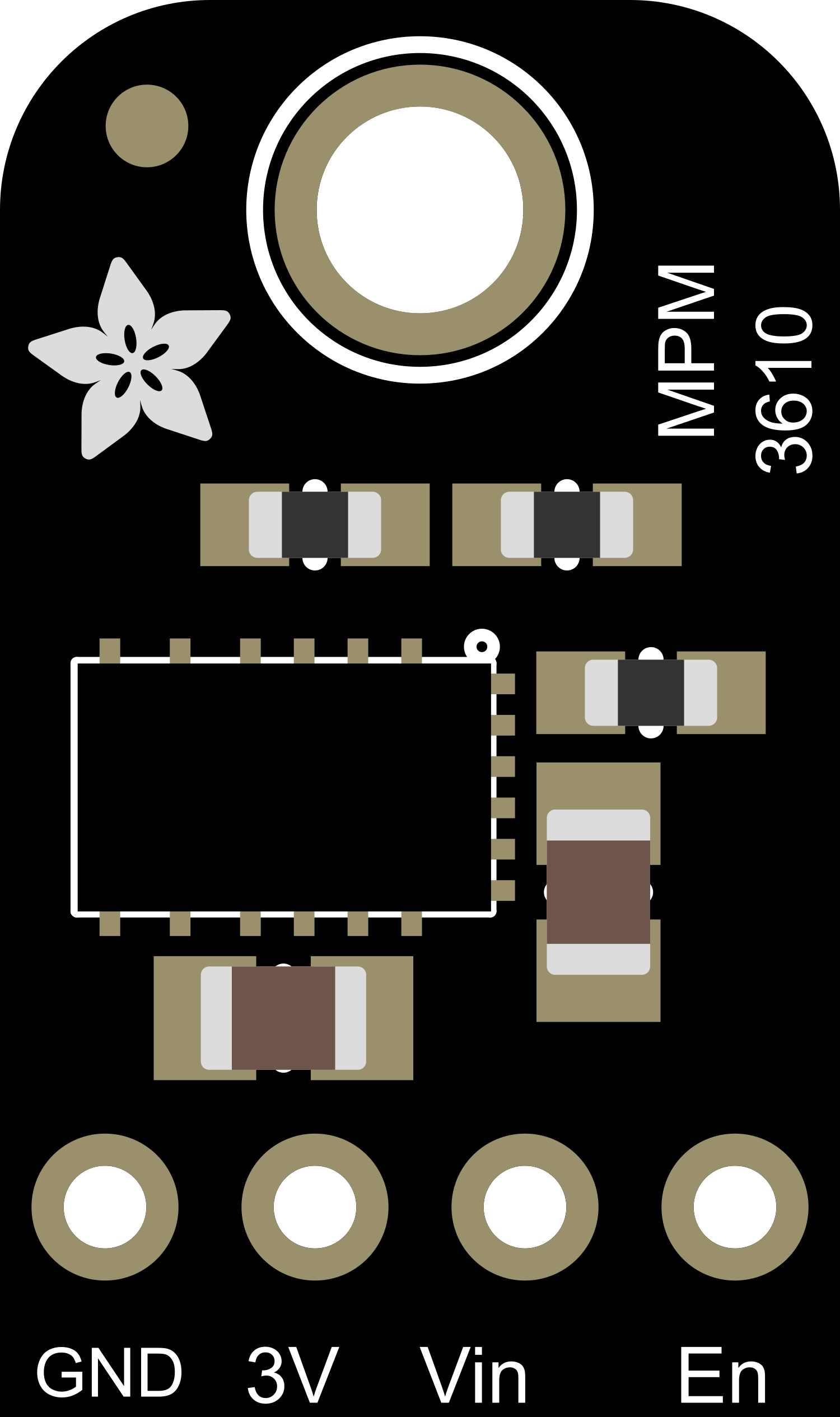
The Adafruit MPM3610 is a high-efficiency, step-down (buck) converter module that provides a regulated output voltage from a higher input voltage source. This breakout board is designed to make it easy for hobbyists and engineers to incorporate a reliable power supply into their projects. Common applications include battery-powered devices, portable instruments, and microcontroller-based systems where a stable voltage is required.
Explore Projects Built with Adafruit MPM3610
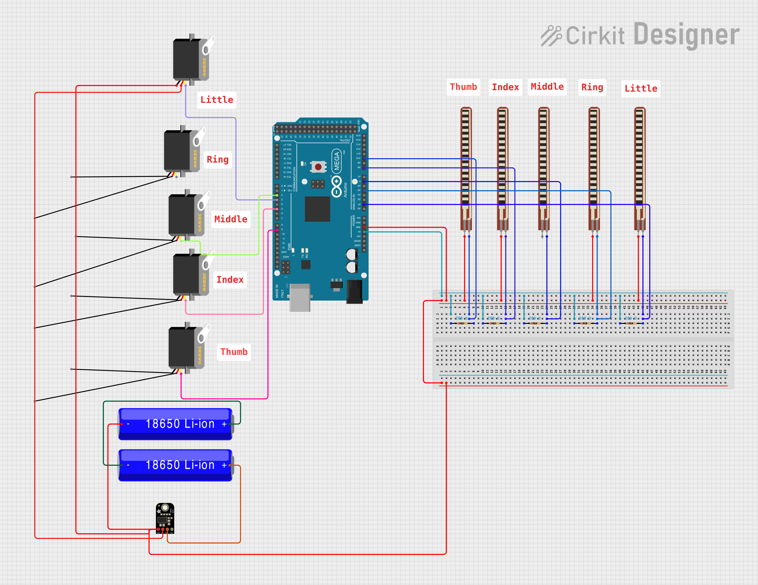

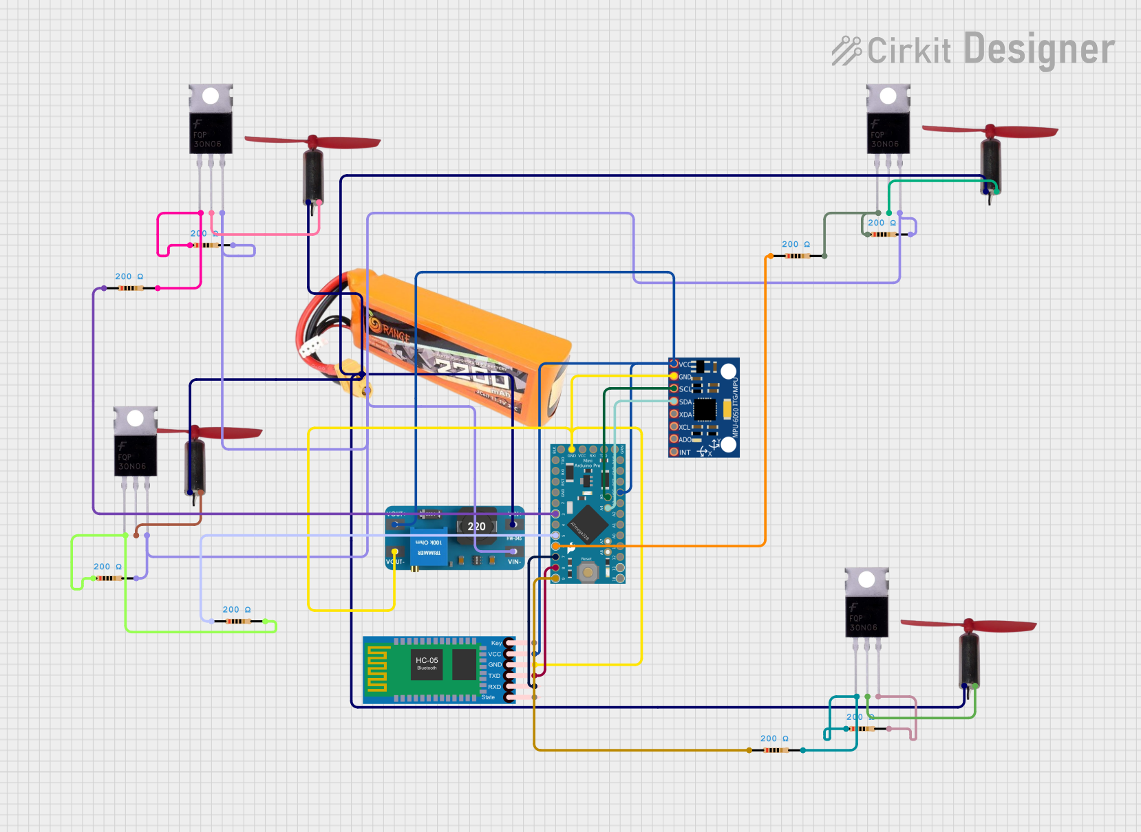

Explore Projects Built with Adafruit MPM3610
Technical Specifications
Key Features
- Input Voltage Range: 6V to 21V
- Output Voltage: 5V fixed
- Maximum Output Current: 1.2A
- High Efficiency: Up to 95%
- Integrated Inductor
- Over-Current and Over-Temperature Protection
- Ultra-small form factor
Pin Configuration and Descriptions
| Pin Number | Name | Description |
|---|---|---|
| 1 | VIN | Input voltage (6V to 21V) |
| 2 | GND | Ground connection |
| 3 | VOUT | Regulated 5V output |
| 4 | EN | Enable pin (active high) |
| 5 | GND | Ground connection |
Usage Instructions
Incorporating into a Circuit
- Connect the input voltage (6V to 21V) to the VIN pin.
- Connect the ground from your power source to one of the GND pins.
- The VOUT pin will provide a regulated 5V output.
- The EN pin can be left unconnected for always-on operation or connected to a logic high signal to enable the module.
Best Practices
- Ensure that the input voltage does not exceed 21V to prevent damage.
- Do not exceed the maximum output current of 1.2A.
- Provide adequate ventilation to the module to prevent overheating.
- Use decoupling capacitors close to the power inputs of sensitive components to minimize voltage spikes.
Example Connection with Arduino UNO
// Example code to demonstrate how to control the Adafruit MPM3610
// with an Arduino UNO for power management.

const int enablePin = 7; // Connect to the EN pin of the MPM3610

void setup() {
  pinMode(enablePin, OUTPUT);
  // Start with the MPM3610 disabled
  digitalWrite(enablePin, LOW);
}

void loop() {
  // Enable the MPM3610 for 5 seconds
  digitalWrite(enablePin, HIGH);
  delay(5000);
  // Disable the MPM3610
  digitalWrite(enablePin, LOW);
  delay(5000);
}
Troubleshooting and FAQs
Common Issues
- No Output Voltage: Ensure that the input voltage is within the specified range and that all connections are secure.
- Output Voltage Drops Under Load: Check if the current draw is within the module's limit of 1.2A.
- Module Overheating: Make sure there is adequate airflow around the module and that it is not enclosed in a small, non-ventilated space.
FAQs
Q: Can I adjust the output voltage of the MPM3610? A: The Adafruit MPM3610 breakout board provides a fixed 5V output and is not adjustable.
Q: What is the efficiency of the MPM3610? A: The efficiency can reach up to 95%, depending on input voltage and load conditions.
Q: How do I enable or disable the MPM3610? A: The module can be enabled or disabled using the EN pin. Apply a logic high signal to enable the module and a logic low signal or leave it unconnected to disable it.
Q: Is the MPM3610 protected against reverse polarity? A: No, the MPM3610 does not have built-in reverse polarity protection. Always ensure correct polarity when connecting the input voltage.
This documentation provides a comprehensive guide to using the Adafruit MPM3610 breakout board. For further assistance or more advanced applications, consult the datasheet or contact technical support.