
How to Use STM32: Examples, Pinouts, and Specs
 Design with STM32 in Cirkit Designer
Introduction
The STM32 is a family of 32-bit microcontrollers developed by STMicroelectronics. These microcontrollers are based on the ARM Cortex-M architecture, offering a balance of high performance, low power consumption, and a rich set of peripherals. STM32 microcontrollers are widely used in embedded systems, including industrial automation, IoT devices, consumer electronics, and motor control applications.
Common applications of STM32 microcontrollers include:
- Real-time control systems
- Wearable devices and IoT sensors
- Robotics and motor control
- Audio processing and multimedia devices
- Communication systems (e.g., CAN, USB, Ethernet)
Explore Projects Built with STM32
 Open Project in Cirkit Designer
 Open Project in Cirkit Designer
 Open Project in Cirkit Designer
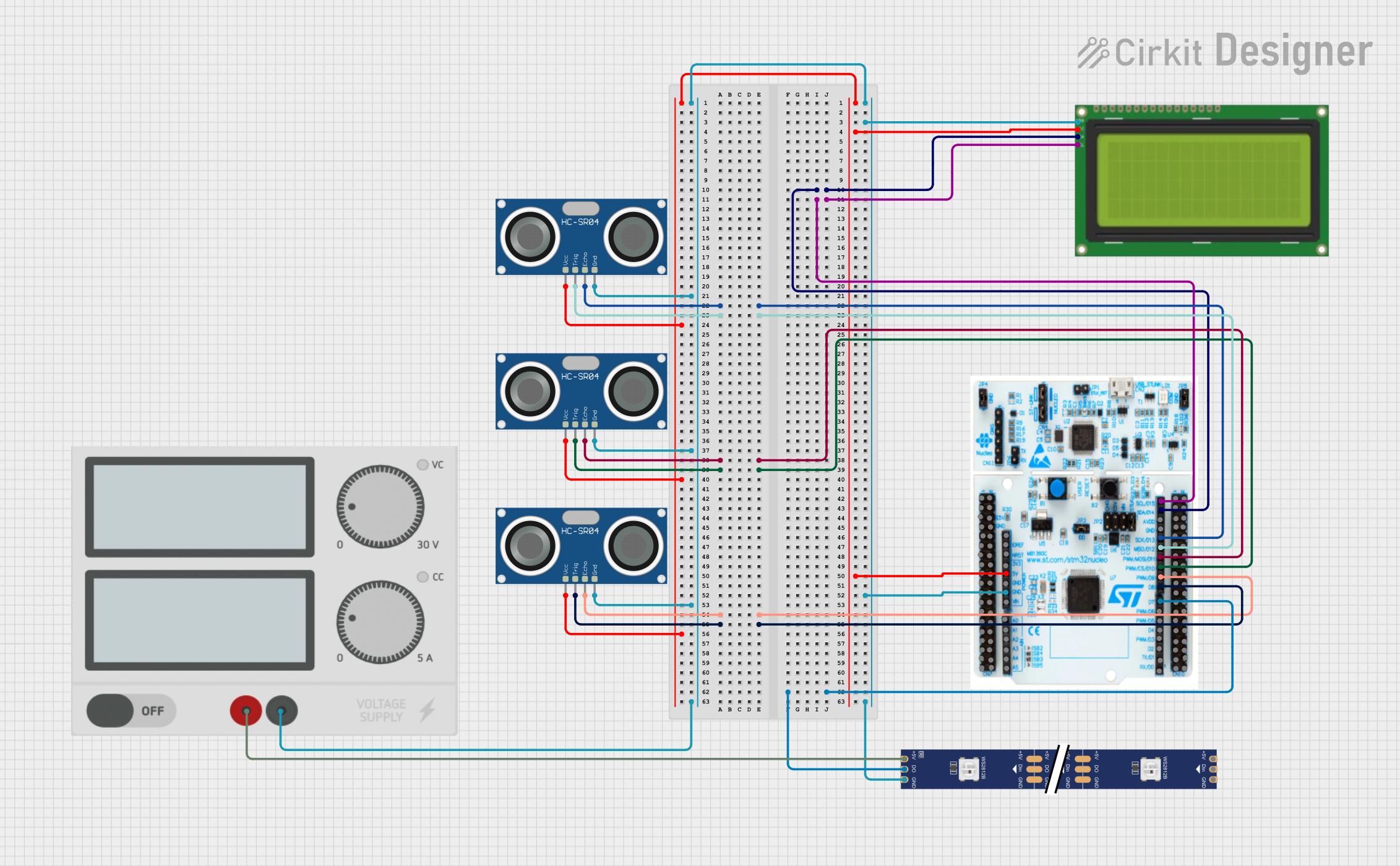 Open Project in Cirkit Designer
Explore Projects Built with STM32
Open Project in Cirkit DesignerOpen Project in Cirkit DesignerOpen Project in Cirkit DesignerOpen Project in Cirkit DesignerTechnical Specifications
The STM32 family includes a wide range of microcontrollers with varying specifications. Below are the general technical details for the STM32 series:
Key Technical Details
- Core Architecture: ARM Cortex-M (M0, M0+, M3, M4, M7, or M33 depending on the model)
- Operating Voltage: 1.8V to 3.6V
- Clock Speed: Up to 480 MHz (depending on the model)
- Flash Memory: 16 KB to 2 MB
- RAM: 4 KB to 1 MB
- GPIO Pins: Up to 168 (depending on the package)
- Communication Interfaces: UART, SPI, I2C, CAN, USB, Ethernet, etc.
- Timers: General-purpose, advanced, and low-power timers
- ADC/DAC: Up to 16-bit ADC and 12-bit DAC
- Power Modes: Sleep, Stop, and Standby for low-power operation
- Package Options: LQFP, BGA, WLCSP, etc.
Pin Configuration and Descriptions
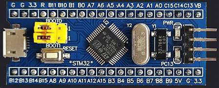
The pin configuration varies depending on the specific STM32 model and package. Below is an example pinout for the STM32F103C8T6 (commonly used in development boards like the "Blue Pill"):
| Pin Name | Function | Description |
|---|---|---|
| PA0-PA15 | GPIO, ADC, Timer, etc. | General-purpose I/O pins with alternate functions |
| PB0-PB15 | GPIO, I2C, SPI, etc. | General-purpose I/O pins with alternate functions |
| PC13-PC15 | GPIO | General-purpose I/O pins |
| VDD | Power Supply | Positive power supply (3.3V) |
| VSS | Ground | Ground connection |
| NRST | Reset | Active-low reset pin |
| BOOT0 | Boot Mode Selection | Selects boot mode (Flash, RAM, or System Memory) |
| OSC_IN/OUT | External Oscillator | Pins for external clock source |
Refer to the datasheet of your specific STM32 model for the complete pinout and alternate functions.
Usage Instructions
How to Use the STM32 in a Circuit
- Power Supply: Provide a stable 3.3V power supply to the VDD pin and connect the VSS pin to ground.
- Clock Configuration: Use an external crystal oscillator (e.g., 8 MHz) or the internal RC oscillator for the system clock.
- Boot Mode Selection: Configure the BOOT0 pin to select the desired boot mode:
- Flash memory (default)
- System memory (for programming via UART)
- SRAM (for debugging)
- Programming: Use an ST-Link programmer/debugger or a USB-to-serial adapter to upload firmware. STM32 microcontrollers support multiple programming interfaces, including SWD, JTAG, and UART.
- Peripherals: Connect peripherals (e.g., sensors, actuators) to the GPIO pins and configure the pins for the desired alternate functions in the firmware.
Important Considerations and Best Practices
- Decoupling Capacitors: Place decoupling capacitors (e.g., 0.1 µF) close to the VDD pins to reduce noise.
- Reset Circuit: Use a pull-up resistor (e.g., 10 kΩ) on the NRST pin to ensure proper reset behavior.
- Clock Stability: If using an external crystal oscillator, include load capacitors as specified in the datasheet.
- Debugging: Reserve the SWD or JTAG pins for debugging and firmware updates.
- Low-Power Modes: Utilize the low-power modes (Sleep, Stop, Standby) to optimize power consumption in battery-powered applications.
Example Code for STM32 with Arduino IDE
The STM32 can be programmed using the Arduino IDE with the STM32duino core. Below is an example of blinking an LED connected to pin PC13 on an STM32F103C8T6:
// Blink an LED on PC13 using STM32 and Arduino IDE

// Define the LED pin
#define LED_PIN PC13

void setup() {
  pinMode(LED_PIN, OUTPUT); // Set PC13 as an output pin
}

void loop() {
  digitalWrite(LED_PIN, HIGH); // Turn the LED on
  delay(1000);                 // Wait for 1 second
  digitalWrite(LED_PIN, LOW);  // Turn the LED off
  delay(1000);                 // Wait for 1 second
}
Note: Ensure that the STM32duino core is installed in the Arduino IDE, and select the correct board and upload method in the Tools menu.
Troubleshooting and FAQs
Common Issues and Solutions
The microcontroller does not power on:
- Verify the power supply voltage (should be 3.3V).
- Check for proper connections to the VDD and VSS pins.
- Ensure decoupling capacitors are placed near the power pins.
Unable to upload firmware:
- Confirm that the BOOT0 pin is set correctly for programming mode.
- Check the connection between the STM32 and the programmer (e.g., ST-Link or USB-to-serial adapter).
- Ensure the correct COM port and board are selected in the programming software.
Peripherals not working as expected:
- Verify the pin configuration in the firmware matches the hardware connections.
- Check for conflicts between alternate functions on the same pin.
- Ensure proper initialization of the peripheral in the code.
High power consumption:
- Use low-power modes (Sleep, Stop, Standby) when the microcontroller is idle.
- Disable unused peripherals in the firmware.
FAQs
Q: Can I program the STM32 using USB?
A: Some STM32 models support USB programming via the DFU (Device Firmware Upgrade) mode. You may need to install the appropriate USB drivers.Q: What is the difference between the STM32F and STM32L series?
A: The STM32F series focuses on performance, while the STM32L series is optimized for low-power applications.Q: How do I select the right STM32 model for my project?
A: Consider factors such as required performance, memory size, peripheral set, and power consumption. Use STMicroelectronics' product selector tool for guidance.Q: Can I use the STM32 with 5V logic?
A: STM32 microcontrollers operate at 3.3V logic levels. Use level shifters if interfacing with 5V devices.
By following this documentation, you can effectively integrate STM32 microcontrollers into your embedded systems projects. For more detailed information, refer to the official datasheets and reference manuals provided by STMicroelectronics.