How to Use motor controller: Examples, Pinouts, and Specs
Introduction
A motor controller is an electronic device that manages the operation of an electric motor by controlling its speed, direction, and torque. It acts as an interface between the motor and the control system, enabling precise and efficient motor operation. Motor controllers are widely used in applications such as robotics, automotive systems, industrial machinery, and home automation. They are essential for tasks requiring variable motor speeds, bidirectional control, or torque regulation.
Explore Projects Built with motor controller

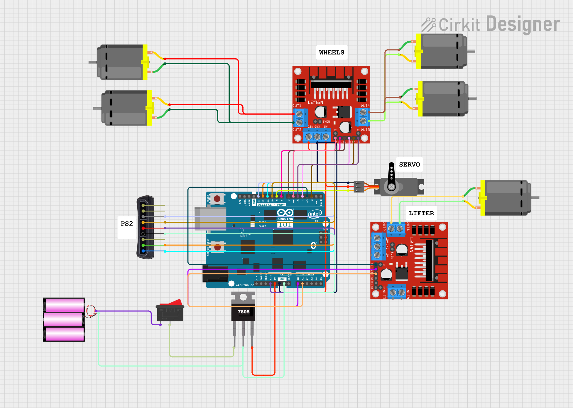
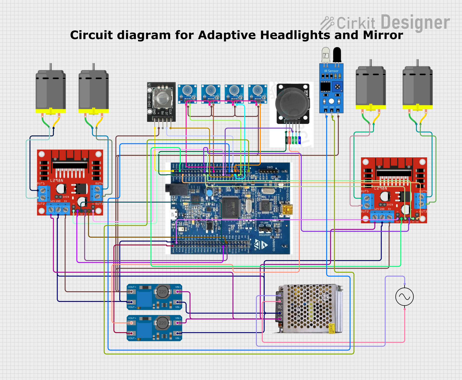
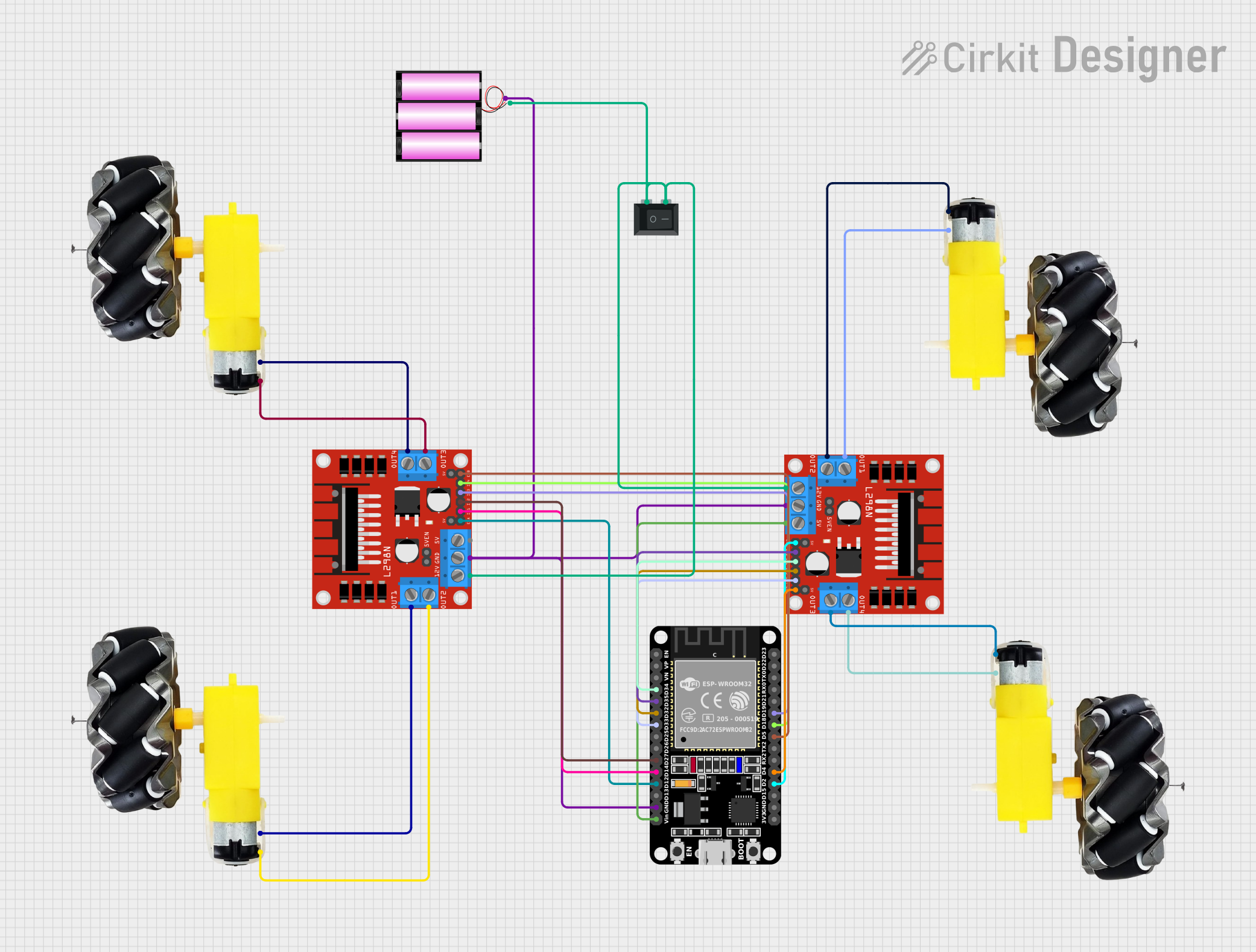
Explore Projects Built with motor controller
Technical Specifications
Below are the general technical specifications for a typical motor controller. Note that specific values may vary depending on the model and manufacturer.
Key Technical Details
- Input Voltage Range: 6V to 36V (varies by model)
- Output Current: Up to 30A (continuous), depending on the controller
- Control Modes: PWM (Pulse Width Modulation), analog, or serial communication
- Supported Motors: DC motors, stepper motors, or brushless motors
- Direction Control: Forward and reverse
- Protection Features: Overcurrent, overvoltage, thermal shutdown, and short-circuit protection
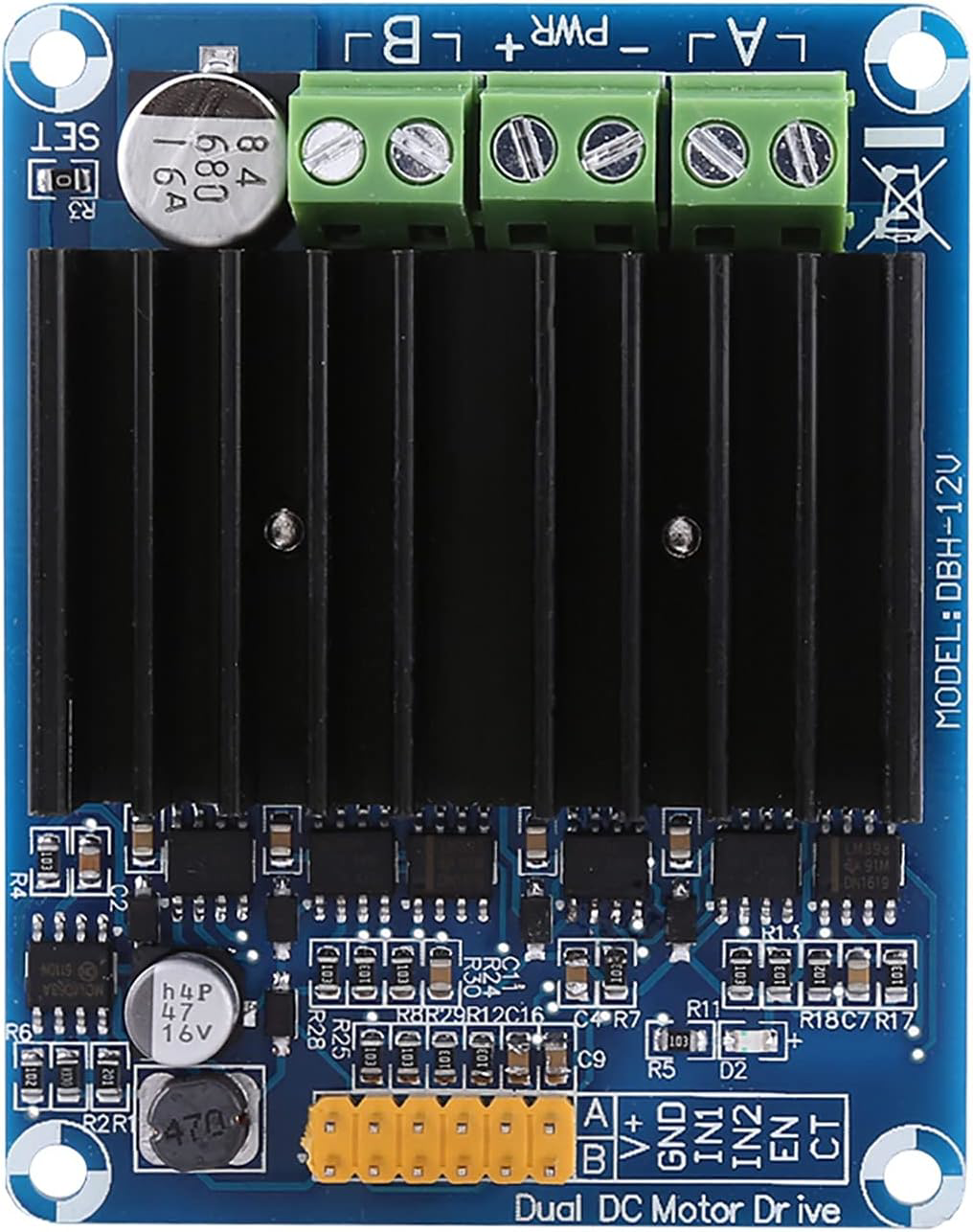
Pin Configuration and Descriptions
The pin configuration for a typical motor controller is as follows:
Table 1: Input Pins
| Pin Name | Description |
|---|---|
| VIN | Power supply input for the motor |
| GND | Ground connection |
| EN | Enable pin to activate the motor driver |
| PWM | Pulse Width Modulation input for speed control |
| DIR | Direction control input (high/low for forward/reverse) |
| VCC | Logic voltage input for the control circuit |
Table 2: Output Pins
| Pin Name | Description |
|---|---|
| OUT1 | Motor output terminal 1 |
| OUT2 | Motor output terminal 2 |
Usage Instructions
How to Use the Component in a Circuit
- Power Supply: Connect the VIN pin to a suitable power source (e.g., battery or DC power supply) within the specified voltage range. Connect the GND pin to the ground of the power source.
- Motor Connection: Attach the motor terminals to the OUT1 and OUT2 pins. Ensure proper wiring to avoid short circuits.
- Control Signals:
- Use the EN pin to enable or disable the motor controller.
- Apply a PWM signal to the PWM pin to control the motor speed. The duty cycle of the PWM signal determines the speed.
- Use the DIR pin to set the motor's direction. For example, a high signal may indicate forward, and a low signal may indicate reverse.
- Logic Voltage: If required, provide a logic voltage (e.g., 5V) to the VCC pin for the control circuit.
Important Considerations and Best Practices
- Heat Dissipation: Ensure proper heat dissipation by using a heatsink or fan if the motor controller operates at high currents.
- Current Ratings: Do not exceed the maximum current rating of the motor controller to avoid damage.
- Decoupling Capacitors: Add decoupling capacitors near the VIN pin to reduce noise and voltage spikes.
- Isolation: For safety, consider using optocouplers or isolation circuits when interfacing with microcontrollers.
Example: Connecting to an Arduino UNO
Below is an example of how to control a motor using an Arduino UNO and a motor controller.
Circuit Connections
- Connect the motor controller's VIN and GND to a 12V power supply.
- Connect the motor terminals to OUT1 and OUT2.
- Connect the EN pin to Arduino pin 7.
- Connect the PWM pin to Arduino pin 9.
- Connect the DIR pin to Arduino pin 8.
- Connect the motor controller's GND to the Arduino GND.
Arduino Code
// Motor Controller Example Code for Arduino UNO
// This code controls motor speed and direction using PWM and digital pins.

#define EN_PIN 7    // Enable pin for the motor controller
#define PWM_PIN 9   // PWM pin for speed control
#define DIR_PIN 8   // Direction control pin

void setup() {
  pinMode(EN_PIN, OUTPUT);  // Set EN pin as output
  pinMode(PWM_PIN, OUTPUT); // Set PWM pin as output
  pinMode(DIR_PIN, OUTPUT); // Set DIR pin as output

  digitalWrite(EN_PIN, HIGH); // Enable the motor controller
}

void loop() {
  // Set motor direction to forward
  digitalWrite(DIR_PIN, HIGH);

  // Gradually increase motor speed
  for (int speed = 0; speed <= 255; speed += 5) {
    analogWrite(PWM_PIN, speed); // Set PWM duty cycle
    delay(100);                  // Wait for 100ms
  }

  // Set motor direction to reverse
  digitalWrite(DIR_PIN, LOW);

  // Gradually decrease motor speed
  for (int speed = 255; speed >= 0; speed -= 5) {
    analogWrite(PWM_PIN, speed); // Set PWM duty cycle
    delay(100);                  // Wait for 100ms
  }
}
Troubleshooting and FAQs
Common Issues and Solutions
Motor Not Running:
- Ensure the EN pin is set to HIGH to enable the motor controller.
- Verify that the power supply voltage matches the motor controller's requirements.
- Check all connections for loose wires or incorrect wiring.
Motor Running in the Wrong Direction:
- Verify the logic level on the DIR pin. Swap the motor terminals if necessary.
Overheating:
- Ensure the motor controller is not exceeding its current rating.
- Add a heatsink or fan for better heat dissipation.
PWM Signal Not Working:
- Confirm that the PWM pin is receiving a valid PWM signal from the microcontroller.
- Check the duty cycle of the PWM signal to ensure it is within the expected range.
FAQs
Can I use this motor controller with a stepper motor?
- No, this motor controller is designed for DC motors. Use a dedicated stepper motor driver for stepper motors.
What happens if I reverse the power supply polarity?
- Most motor controllers include reverse polarity protection, but it is best to double-check the datasheet. Always connect the power supply correctly.
Can I control multiple motors with one controller?
- Some motor controllers support dual-channel operation for controlling two motors. Check the specifications of your motor controller.
By following this documentation, you can effectively use a motor controller in your projects and troubleshoot common issues.