How to Use Timer 24h: Examples, Pinouts, and Specs
Introduction
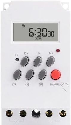
The Timer 24h is a versatile electronic component designed to count up or down for a maximum duration of 24 hours. It is commonly used in applications requiring precise time management, such as cooking appliances, automation systems, scheduling tasks, and industrial processes. This timer provides reliable and accurate timekeeping, making it an essential component in both consumer and industrial electronics.
Explore Projects Built with Timer 24h
Explore Projects Built with Timer 24h
Technical Specifications
- Operating Voltage: 3V to 12V DC
- Current Consumption: < 50mA
- Maximum Timing Duration: 24 hours
- Timing Modes: Count-up and count-down
- Display Type: 7-segment or LCD (depending on the model)
- Control Interface: Push buttons or external microcontroller
- Accuracy: ±1 second per 24 hours
- Operating Temperature: -10°C to 60°C
- Dimensions: 50mm x 30mm x 15mm (typical)
Pin Configuration and Descriptions
The Timer 24h typically comes with a 6-pin interface. Below is the pinout and description:
| Pin | Name | Description |
|---|---|---|
| 1 | VCC | Power supply input (3V to 12V DC). |
| 2 | GND | Ground connection. |
| 3 | START/STOP | Input pin to start or stop the timer. |
| 4 | MODE | Input pin to toggle between count-up and count-down modes. |
| 5 | RESET | Input pin to reset the timer to its initial state. |
| 6 | OUT | Output pin that provides a signal (e.g., HIGH) when the timer reaches zero. |
Usage Instructions
How to Use the Timer 24h in a Circuit
- Power Connection: Connect the VCC pin to a DC power source (3V to 12V) and the GND pin to the ground.
- Mode Selection: Use the MODE pin to select the desired timing mode:
- Pull the MODE pin HIGH for count-up mode.
- Pull the MODE pin LOW for count-down mode.
- Start/Stop Control: Use the START/STOP pin to begin or pause the timer. A HIGH signal starts the timer, while a LOW signal pauses it.
- Reset Function: To reset the timer, momentarily pull the RESET pin HIGH.
- Output Signal: Monitor the OUT pin for a HIGH signal, which indicates that the timer has completed its countdown.
Important Considerations and Best Practices
- Ensure the power supply voltage is within the specified range to avoid damaging the timer.
- Use pull-up or pull-down resistors on control pins to prevent floating states.
- If connecting the timer to a microcontroller, ensure proper voltage level matching between the timer and the microcontroller.
- For long-duration timing, verify the accuracy of the timer periodically to account for any drift.
Example: Connecting Timer 24h to an Arduino UNO
Below is an example of how to use the Timer 24h with an Arduino UNO to control an LED when the timer reaches zero.
// Define pin connections for the Timer 24h
const int startStopPin = 2;  // Arduino pin connected to START/STOP pin of the timer
const int modePin = 3;       // Arduino pin connected to MODE pin of the timer
const int resetPin = 4;      // Arduino pin connected to RESET pin of the timer
const int outPin = 5;        // Arduino pin connected to OUT pin of the timer
const int ledPin = 13;       // Arduino pin connected to an LED

void setup() {
  // Set pin modes
  pinMode(startStopPin, OUTPUT);
  pinMode(modePin, OUTPUT);
  pinMode(resetPin, OUTPUT);
  pinMode(outPin, INPUT);
  pinMode(ledPin, OUTPUT);

  // Initialize the timer in count-down mode
  digitalWrite(modePin, LOW);  // Set mode to count-down
  digitalWrite(resetPin, HIGH);  // Reset the timer
  delay(100);  // Short delay to ensure reset
  digitalWrite(resetPin, LOW);

  // Start the timer
  digitalWrite(startStopPin, HIGH);
}

void loop() {
  // Check if the timer has reached zero
  if (digitalRead(outPin) == HIGH) {
    digitalWrite(ledPin, HIGH);  // Turn on the LED
    delay(1000);  // Keep the LED on for 1 second
    digitalWrite(ledPin, LOW);   // Turn off the LED
  }
}
Troubleshooting and FAQs
Common Issues and Solutions
Timer Does Not Start
- Cause: The START/STOP pin is not properly connected or not receiving a HIGH signal.
- Solution: Verify the connection to the START/STOP pin and ensure it is pulled HIGH to start the timer.
Incorrect Timing
- Cause: Power supply voltage is unstable or out of range.
- Solution: Use a stable DC power source within the specified voltage range (3V to 12V).
Output Signal Not Detected
- Cause: OUT pin is not properly connected or monitored.
- Solution: Check the connection to the OUT pin and ensure it is being read correctly by the circuit or microcontroller.
Timer Resets Unexpectedly
- Cause: Noise or interference on the RESET pin.
- Solution: Add a pull-down resistor to the RESET pin to prevent accidental triggering.
FAQs
Q: Can the Timer 24h operate on a 5V power supply?
A: Yes, the Timer 24h can operate on a 5V DC power supply, as it supports a voltage range of 3V to 12V.Q: How accurate is the Timer 24h over long durations?
A: The timer has an accuracy of ±1 second per 24 hours, making it suitable for most applications requiring precise timing.Q: Can I use the Timer 24h with a 3.3V microcontroller?
A: Yes, the Timer 24h is compatible with 3.3V systems, provided the power supply voltage matches the microcontroller's logic level.Q: What happens if the power supply is interrupted?
A: The timer will reset, and the timing operation will need to be restarted. Consider using a backup power source for critical applications.