Cirkit Designer
Your all-in-one circuit design IDE
Home /
Component Documentation
How to Use ESP 32 Symbol: Examples, Pinouts, and Specs
Introduction
The ESP32 is a low-cost, low-power system on a chip (SoC) series with Wi-Fi and dual-mode Bluetooth capabilities. It is widely used in IoT applications for its versatility and performance. The ESP32 is designed for mobile devices, wearable electronics, and IoT applications, providing a complete, self-contained Wi-Fi and Bluetooth networking solution.
Explore Projects Built with ESP 32 Symbol
ESP32-Based RF Communication System with 433 MHz Modules

This circuit comprises an ESP32 microcontroller connected to a 433 MHz RF transmitter and receiver pair. The ESP32 is programmed to receive and decode RF signals through the receiver module, as well as send RF signals via the transmitter module. Additionally, the ESP32 can communicate with a Bluetooth device to exchange commands and data, and it uses an LED for status indication.
ESP32-Controlled Dual 8x8 LED Matrix Display with NTP Time Synchronization

This circuit features an ESP32 microcontroller connected to two cascaded 8x8 LED matrix displays, powered by a 3.3V battery. The ESP32 drives the displays to show time and other information, with the code indicating functionality for connecting to WiFi, synchronizing time via NTP, and displaying data on the matrices using custom fonts. Additionally, there is a separate 3.3V battery powering a red LED, which appears to function as a simple indicator light.
ESP32-Based Multi-Sensor Monitoring System
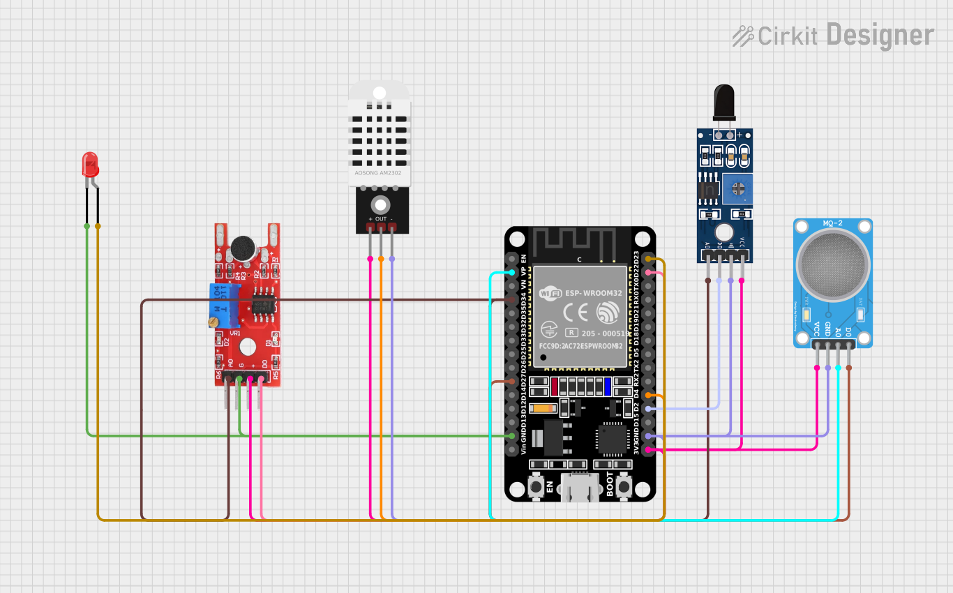
This circuit features an ESP32 microcontroller connected to various sensors: an MQ-2 gas sensor, a KY-038 sound sensor, a DHT22 temperature and humidity sensor, and an SHT113 flame sensor. The ESP32 reads analog signals from the MQ-2, KY-038, and SHT113 sensors, and digital signals from the MQ-2, KY-038, SHT113, and DHT22 sensors. Additionally, there is a red LED that can be controlled by the ESP32, likely for indicating status or alerts.
ESP32-Based Carbon Monoxide Detector with OLED Display and Alert System
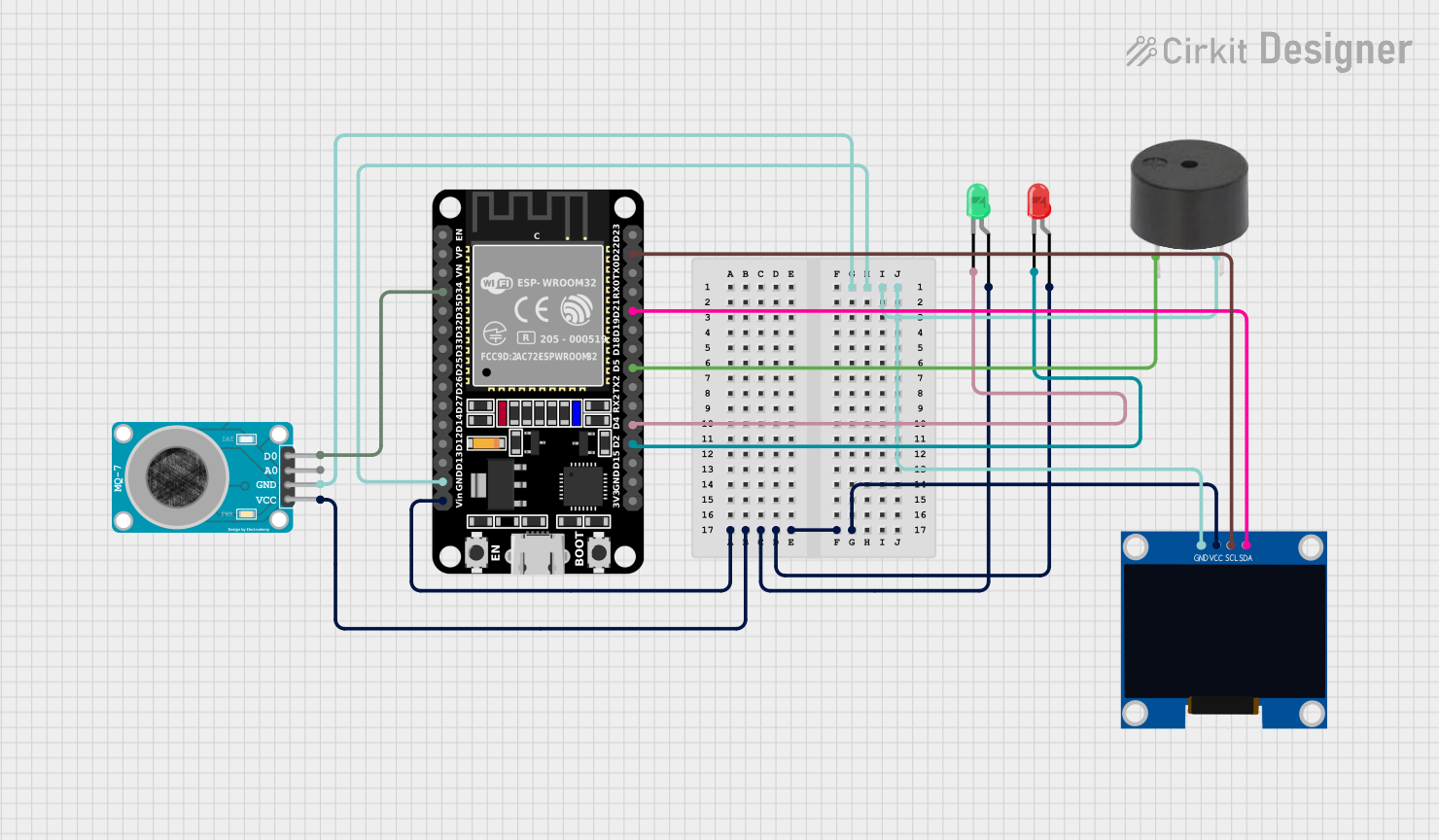
This circuit features an ESP32 microcontroller connected to various peripherals. It includes a buzzer controlled by the ESP32, a 128x64 OLED display interfaced via I2C (with SDA and SCL lines connected), and an MQ-7 carbon monoxide gas sensor with its digital output connected to the ESP32. Additionally, there are two LEDs (red and green) with their anodes connected to the power supply and cathodes controlled by GPIO pins of the ESP32 for status indication.
Explore Projects Built with ESP 32 Symbol
ESP32-Based RF Communication System with 433 MHz Modules
This circuit comprises an ESP32 microcontroller connected to a 433 MHz RF transmitter and receiver pair. The ESP32 is programmed to receive and decode RF signals through the receiver module, as well as send RF signals via the transmitter module. Additionally, the ESP32 can communicate with a Bluetooth device to exchange commands and data, and it uses an LED for status indication.
ESP32-Controlled Dual 8x8 LED Matrix Display with NTP Time Synchronization
This circuit features an ESP32 microcontroller connected to two cascaded 8x8 LED matrix displays, powered by a 3.3V battery. The ESP32 drives the displays to show time and other information, with the code indicating functionality for connecting to WiFi, synchronizing time via NTP, and displaying data on the matrices using custom fonts. Additionally, there is a separate 3.3V battery powering a red LED, which appears to function as a simple indicator light.
ESP32-Based Multi-Sensor Monitoring System
This circuit features an ESP32 microcontroller connected to various sensors: an MQ-2 gas sensor, a KY-038 sound sensor, a DHT22 temperature and humidity sensor, and an SHT113 flame sensor. The ESP32 reads analog signals from the MQ-2, KY-038, and SHT113 sensors, and digital signals from the MQ-2, KY-038, SHT113, and DHT22 sensors. Additionally, there is a red LED that can be controlled by the ESP32, likely for indicating status or alerts.
ESP32-Based Carbon Monoxide Detector with OLED Display and Alert System
This circuit features an ESP32 microcontroller connected to various peripherals. It includes a buzzer controlled by the ESP32, a 128x64 OLED display interfaced via I2C (with SDA and SCL lines connected), and an MQ-7 carbon monoxide gas sensor with its digital output connected to the ESP32. Additionally, there are two LEDs (red and green) with their anodes connected to the power supply and cathodes controlled by GPIO pins of the ESP32 for status indication.
Common Applications and Use Cases
- Home Automation: Control and monitor home appliances remotely.
- Wearable Electronics: Integrate into smartwatches and fitness trackers.
- Industrial Automation: Monitor and control industrial processes.
- Smart Agriculture: Collect and analyze data from agricultural sensors.
- Health Monitoring: Develop health monitoring devices and systems.
Technical Specifications
Key Technical Details
| Specification | Value |
|---|---|
| Operating Voltage | 2.2V - 3.6V |
| Operating Current | 80mA (average) |
| Power Consumption | 5µA (deep sleep mode) |
| Wi-Fi Standards | 802.11 b/g/n |
| Bluetooth | v4.2 BR/EDR and BLE |
| CPU | Xtensa® Dual-Core 32-bit LX6 |
| Flash Memory | 4MB (external) |
| SRAM | 520KB |
| GPIO Pins | 34 |
| Communication | UART, SPI, I2C, I2S, CAN, PWM, ADC, DAC |
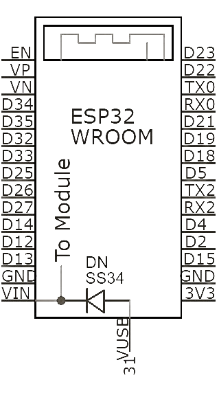
Pin Configuration and Descriptions
| Pin Number | Pin Name | Description |
|---|---|---|
| 1 | EN | Enable (Active High) |
| 2 | IO0 | GPIO0, Boot Mode Select |
| 3 | IO1 | GPIO1, UART0 TXD |
| 4 | IO2 | GPIO2 |
| 5 | IO3 | GPIO3, UART0 RXD |
| 6 | IO4 | GPIO4 |
| 7 | IO5 | GPIO5 |
| 8 | GND | Ground |
| 9 | 3V3 | 3.3V Power Supply |
| 10 | IO12 | GPIO12, HSPI MISO |
| 11 | IO13 | GPIO13, HSPI MOSI |
| 12 | IO14 | GPIO14, HSPI CLK |
| 13 | IO15 | GPIO15, HSPI CS0 |
| 14 | IO16 | GPIO16, UART2 RXD |
| 15 | IO17 | GPIO17, UART2 TXD |
| 16 | IO18 | GPIO18, VSPI CLK |
| 17 | IO19 | GPIO19, VSPI MISO |
| 18 | IO21 | GPIO21, I2C SDA |
| 19 | IO22 | GPIO22, I2C SCL |
| 20 | IO23 | GPIO23, VSPI MOSI |
| 21 | IO25 | GPIO25, DAC1 |
| 22 | IO26 | GPIO26, DAC2 |
| 23 | IO27 | GPIO27 |
| 24 | IO32 | GPIO32, ADC1_CH4 |
| 25 | IO33 | GPIO33, ADC1_CH5 |
| 26 | IO34 | GPIO34, ADC1_CH6 |
| 27 | IO35 | GPIO35, ADC1_CH7 |
| 28 | IO36 | GPIO36, ADC1_CH0 |
| 29 | IO39 | GPIO39, ADC1_CH3 |
Usage Instructions
How to Use the Component in a Circuit
- Power Supply: Connect the 3V3 pin to a 3.3V power supply and the GND pin to ground.
- GPIO Pins: Use the GPIO pins for digital input/output operations. Configure them as needed in your code.
- Communication Interfaces: Utilize UART, SPI, I2C, and other communication interfaces for connecting to other devices.
- Wi-Fi and Bluetooth: Use the built-in Wi-Fi and Bluetooth capabilities for wireless communication.
Important Considerations and Best Practices
- Power Supply: Ensure a stable 3.3V power supply to avoid damage to the ESP32.
- Boot Mode: Use GPIO0 to select the boot mode. Pull it low to enter the bootloader mode.
- Deep Sleep Mode: Utilize deep sleep mode to save power in battery-operated applications.
- Antenna Placement: Ensure proper antenna placement for optimal Wi-Fi and Bluetooth performance.
Example Code for Arduino UNO
#include <WiFi.h>

// Replace with your network credentials
const char* ssid = "your_SSID";
const char* password = "your_PASSWORD";

void setup() {
  Serial.begin(115200);

  // Connect to Wi-Fi
  WiFi.begin(ssid, password);

  // Wait for connection
  while (WiFi.status() != WL_CONNECTED) {
    delay(1000);
    Serial.println("Connecting to WiFi...");
  }

  Serial.println("Connected to WiFi");
}

void loop() {
  // Put your main code here, to run repeatedly
}
Troubleshooting and FAQs
Common Issues Users Might Face
ESP32 Not Connecting to Wi-Fi:
- Solution: Check the SSID and password. Ensure the Wi-Fi network is within range.
GPIO Pins Not Responding:
- Solution: Verify the pin configuration in your code. Ensure the pins are not being used for other functions.
Power Issues:
- Solution: Ensure a stable 3.3V power supply. Check for loose connections.
Boot Mode Issues:
- Solution: Ensure GPIO0 is correctly configured for the desired boot mode.
Solutions and Tips for Troubleshooting
- Serial Monitor: Use the Serial Monitor to debug and print messages for troubleshooting.
- Multimeter: Use a multimeter to check voltage levels and continuity in your circuit.
- Documentation: Refer to the ESP32 datasheet and reference manual for detailed information.
By following this documentation, users can effectively utilize the ESP32 in their projects, leveraging its powerful features for a wide range of applications.