How to Use Stellar H7V2: Examples, Pinouts, and Specs
Introduction
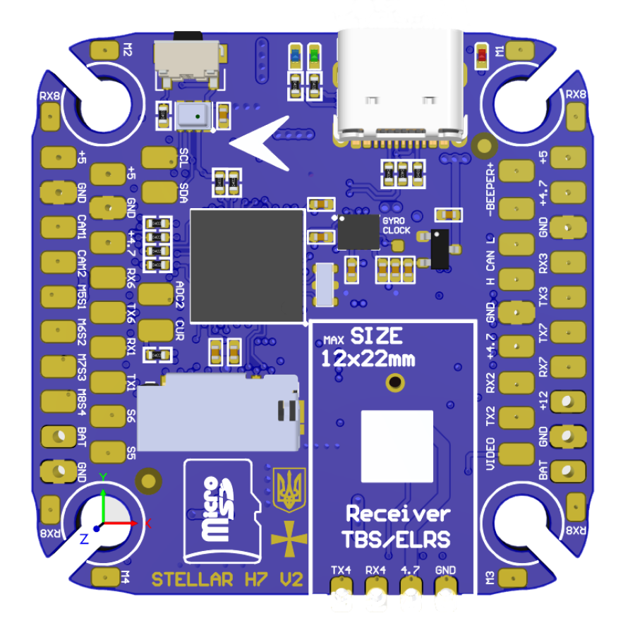
The Stellar H7V2, manufactured by StngBee, is a high-performance microcontroller tailored for advanced embedded systems. It features a powerful processing core, extensive I/O capabilities, and support for multiple communication protocols. This microcontroller is designed to handle complex applications, making it a preferred choice for robotics, industrial automation, and IoT solutions.
Explore Projects Built with Stellar H7V2
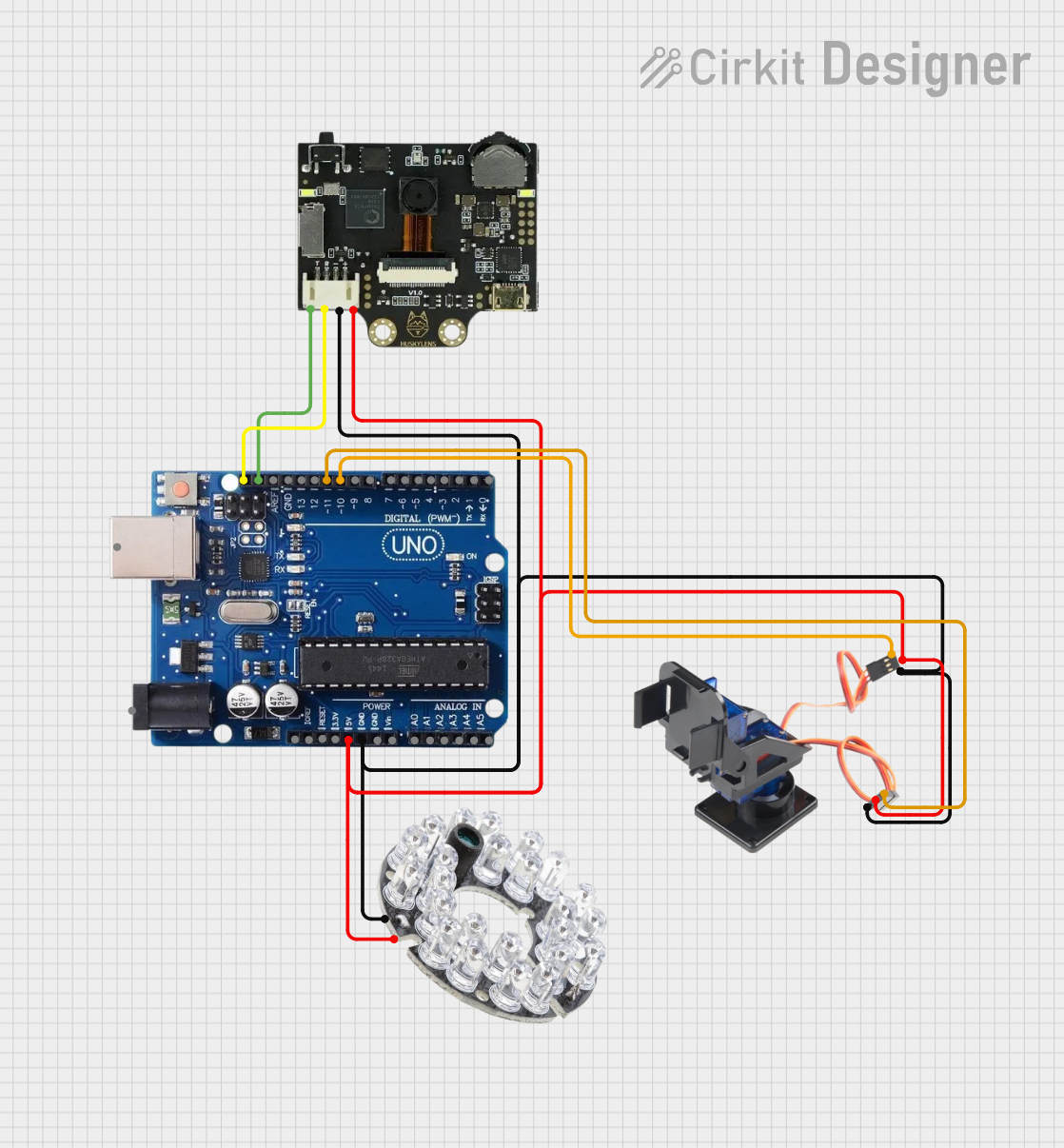


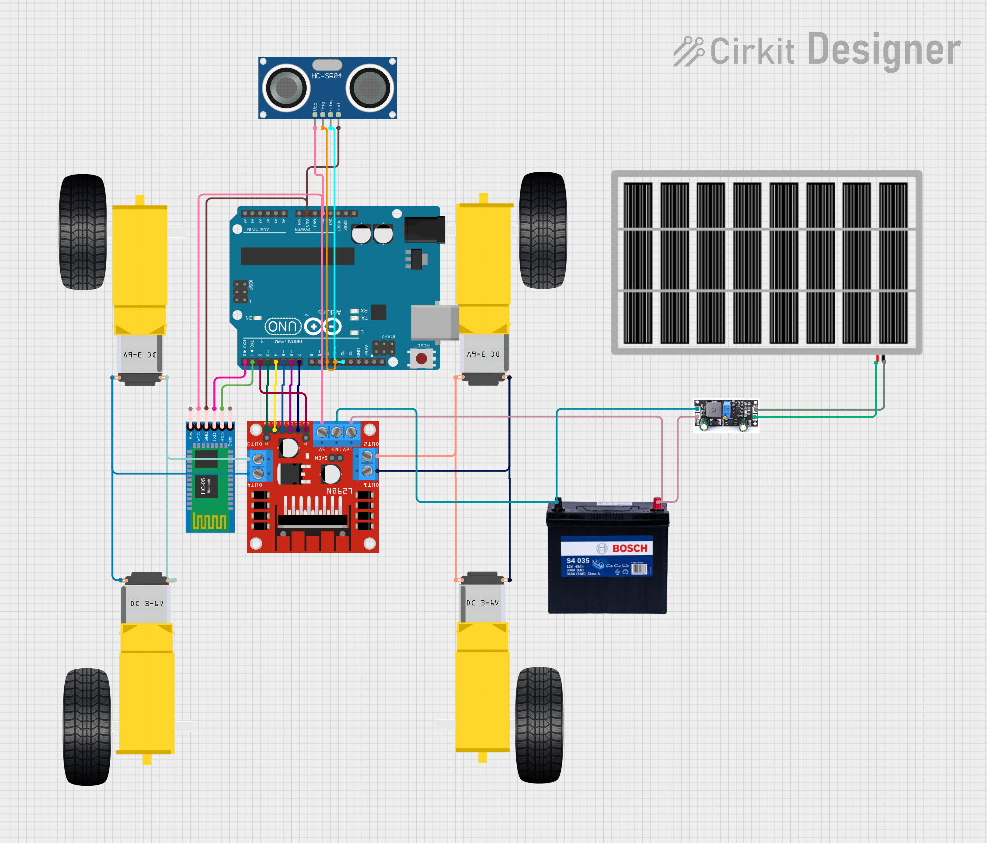
Explore Projects Built with Stellar H7V2
Common Applications
- Robotics and autonomous systems
- Industrial automation and control
- Internet of Things (IoT) devices
- Real-time data processing and analytics
- Advanced motor control systems
Technical Specifications
Key Technical Details
| Parameter | Specification |
|---|---|
| Processor Core | ARM Cortex-M7, 32-bit |
| Clock Speed | Up to 480 MHz |
| Flash Memory | 2 MB |
| RAM | 1 MB |
| Operating Voltage | 3.3V |
| I/O Voltage Range | 1.8V to 3.6V |
| Communication Protocols | UART, SPI, I2C, CAN, USB, Ethernet |
| GPIO Pins | 100 (configurable) |
| ADC Resolution | 12-bit, 16 channels |
| DAC Resolution | 12-bit, 2 channels |
| Timers | 16 (including advanced PWM timers) |
| Power Consumption | 50 mA (typical at 3.3V) |
| Package Type | LQFP-144 |
| Operating Temperature | -40°C to +85°C |
Pin Configuration and Descriptions
The Stellar H7V2 comes in an LQFP-144 package with 144 pins. Below is a summary of key pin functions:
| Pin Number | Pin Name | Description |
|---|---|---|
| 1 | VDD | Power supply (3.3V) |
| 2 | VSS | Ground |
| 10 | PA0 | GPIO/ADC Input/Interrupt (configurable) |
| 20 | PB6 | I2C1_SCL (I2C Clock Line) |
| 21 | PB7 | I2C1_SDA (I2C Data Line) |
| 50 | PC13 | GPIO/User Button Input |
| 70 | PA9 | UART1_TX (Transmit) |
| 71 | PA10 | UART1_RX (Receive) |
| 100 | PA5 | SPI1_SCK (SPI Clock) |
| 101 | PA6 | SPI1_MISO (SPI Data In) |
| 102 | PA7 | SPI1_MOSI (SPI Data Out) |
| 120 | PA15 | GPIO/External Interrupt |
| 144 | NRST | Reset Pin |
For a complete pinout, refer to the official datasheet provided by StngBee.
Usage Instructions
How to Use the Stellar H7V2 in a Circuit
- Power Supply: Connect the VDD pin to a stable 3.3V power source and the VSS pin to ground.
- Clock Configuration: Use an external 8 MHz crystal oscillator for precise timing or configure the internal clock.
- GPIO Setup: Configure GPIO pins as input, output, or alternate functions using the microcontroller's registers or a development library.
- Communication Protocols: Connect peripherals (e.g., sensors, actuators) using supported protocols like UART, SPI, or I2C.
- Programming: Use an SWD (Serial Wire Debug) interface or USB bootloader to upload firmware.
Important Considerations
- Voltage Levels: Ensure all connected devices operate within the 1.8V to 3.6V range to avoid damage.
- Decoupling Capacitors: Place 0.1 µF decoupling capacitors near the VDD pins to stabilize the power supply.
- Reset Circuit: Use an external pull-up resistor (10 kΩ) on the NRST pin for reliable reset functionality.
- Clock Stability: For time-critical applications, use an external crystal oscillator with appropriate load capacitors.
Example: Connecting to an Arduino UNO
The Stellar H7V2 can communicate with an Arduino UNO via UART. Below is an example of how to set up UART communication:
Circuit Connections
| Stellar H7V2 Pin | Arduino UNO Pin |
|---|---|
| PA9 (UART1_TX) | RX (Pin 0) |
| PA10 (UART1_RX) | TX (Pin 1) |
| VDD | 3.3V |
| VSS | GND |
Example Code for Arduino UNO
// Arduino UNO code to communicate with Stellar H7V2 via UART
void setup() {
  Serial.begin(9600); // Initialize UART at 9600 baud rate
  delay(1000);        // Wait for the Stellar H7V2 to initialize
  Serial.println("Hello, Stellar H7V2!"); // Send a message
}

void loop() {
  if (Serial.available()) {
    // Read data from Stellar H7V2 and echo it back
    char received = Serial.read();
    Serial.print("Received: ");
    Serial.println(received);
  }
}
Example Code for Stellar H7V2
// Stellar H7V2 code to communicate with Arduino UNO via UART
#include "stm32h7xx_hal.h" // Include HAL library for STM32H7 series

UART_HandleTypeDef huart1;

void SystemClock_Config(void);
void UART1_Init(void);

int main(void) {
  HAL_Init();                // Initialize the HAL Library
  SystemClock_Config();      // Configure the system clock
  UART1_Init();              // Initialize UART1

  char message[] = "Hello, Arduino UNO!\r\n";

  while (1) {
    // Transmit message to Arduino UNO
    HAL_UART_Transmit(&huart1, (uint8_t *)message, sizeof(message) - 1, HAL_MAX_DELAY);
    HAL_Delay(1000); // Wait 1 second
  }
}

void UART1_Init(void) {
  huart1.Instance = USART1; // Use USART1
  huart1.Init.BaudRate = 9600;
  huart1.Init.WordLength = UART_WORDLENGTH_8B;
  huart1.Init.StopBits = UART_STOPBITS_1;
  huart1.Init.Parity = UART_PARITY_NONE;
  huart1.Init.Mode = UART_MODE_TX_RX;
  huart1.Init.HwFlowCtl = UART_HWCONTROL_NONE;
  huart1.Init.OverSampling = UART_OVERSAMPLING_16;
  HAL_UART_Init(&huart1); // Initialize UART
}
Troubleshooting and FAQs
Common Issues
Microcontroller Not Powering On
- Ensure the VDD pin is connected to a stable 3.3V source.
- Check for proper grounding on the VSS pin.
- Verify the power supply's current rating meets the microcontroller's requirements.
Communication Failure
- Double-check the wiring for UART, SPI, or I2C connections.
- Ensure the baud rate and other communication settings match between devices.
- Use pull-up resistors for I2C lines if not already included.
Unstable Operation
- Verify the decoupling capacitors are correctly placed near the VDD pins.
- Use an external crystal oscillator for better clock stability.
FAQs
Q: Can the Stellar H7V2 operate at 5V?
A: No, the Stellar H7V2 operates within a voltage range of 1.8V to 3.6V. Exceeding this range may damage the microcontroller.
Q: How do I program the Stellar H7V2?
A: You can program the Stellar H7V2 using an SWD programmer or via the USB bootloader.
Q: Does the Stellar H7V2 support real-time operating systems (RTOS)?
A: Yes, the ARM Cortex-M7 core is compatible with popular RTOS platforms like FreeRTOS.
Q: What is the maximum GPIO current?
A: Each GPIO pin can source or sink up to 25 mA, but the total current for all GPIOs should not exceed 120 mA.