How to Use ESP32 38-PIN: Examples, Pinouts, and Specs
Introduction
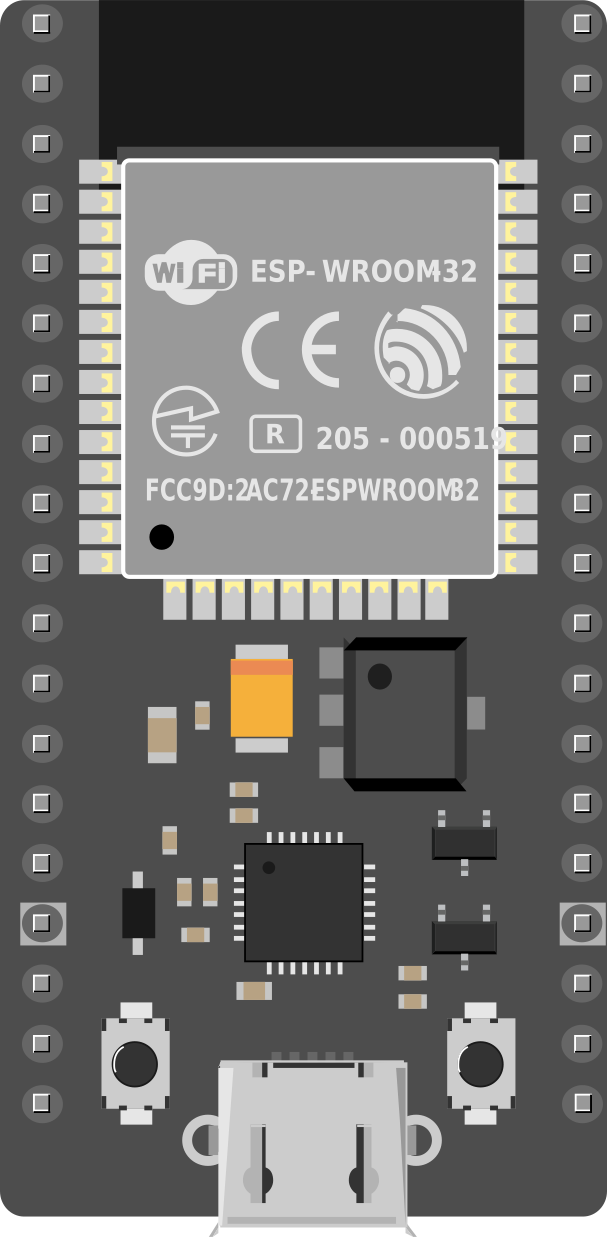
The ESP32 38-PIN is a versatile microcontroller designed for a wide range of applications, particularly in the Internet of Things (IoT) and embedded systems. It features built-in Wi-Fi and Bluetooth capabilities, making it an excellent choice for wireless communication projects. With 38 pins, the ESP32 offers extensive input/output (I/O) options, enabling developers to connect various sensors, actuators, and peripherals.
Explore Projects Built with ESP32 38-PIN


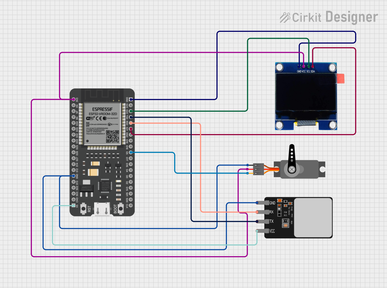
Explore Projects Built with ESP32 38-PIN
Common Applications and Use Cases
- IoT devices and smart home automation
- Wireless sensor networks
- Wearable technology
- Robotics and automation systems
- Data logging and remote monitoring
- Prototyping and educational projects
Technical Specifications
The ESP32 38-PIN microcontroller is packed with features that make it a powerful and flexible component for a variety of projects.
Key Technical Details
- Processor: Dual-core Xtensa® 32-bit LX6 microprocessor
- Clock Speed: Up to 240 MHz
- Flash Memory: 4 MB (varies by model)
- SRAM: 520 KB
- Wi-Fi: 802.11 b/g/n
- Bluetooth: v4.2 BR/EDR and BLE
- Operating Voltage: 3.3V
- Input Voltage Range: 5V (via USB) or 7-12V (via VIN pin)
- GPIO Pins: 34 (multipurpose)
- ADC Channels: 18 (12-bit resolution)
- DAC Channels: 2
- PWM Outputs: 16
- Communication Protocols: UART, SPI, I2C, I2S, CAN, and more
- Power Consumption: Ultra-low power modes available
- Operating Temperature: -40°C to +125°C
Pin Configuration and Descriptions
The ESP32 38-PIN has a total of 38 pins, each with specific functions. Below is a summary of the pin configuration:
| Pin Name | Function | Description |
|---|---|---|
| VIN | Power Input | Accepts 7-12V input for powering the ESP32. |
| 3V3 | Power Output | Provides 3.3V output for external components. |
| GND | Ground | Common ground for the circuit. |
| GPIO0 | General Purpose I/O, Boot Mode | Used for I/O or to enter bootloader mode. |
| GPIO1 (TX) | UART TX | Transmit pin for UART communication. |
| GPIO3 (RX) | UART RX | Receive pin for UART communication. |
| GPIO2 | General Purpose I/O, ADC, PWM | Multipurpose pin with ADC and PWM capabilities. |
| GPIO4 | General Purpose I/O, ADC, PWM | Multipurpose pin with ADC and PWM capabilities. |
| GPIO5 | General Purpose I/O, ADC, PWM | Multipurpose pin with ADC and PWM capabilities. |
| GPIO12-15 | General Purpose I/O, ADC, PWM | Multipurpose pins with ADC and PWM capabilities. |
| GPIO16-19 | General Purpose I/O, SPI, PWM | Multipurpose pins with SPI and PWM capabilities. |
| GPIO21-23 | General Purpose I/O, I2C, PWM | Multipurpose pins with I2C and PWM capabilities. |
| GPIO25-27 | General Purpose I/O, ADC, DAC, PWM | Multipurpose pins with ADC, DAC, and PWM capabilities. |
| GPIO32-39 | General Purpose I/O, ADC, PWM | Multipurpose pins with ADC and PWM capabilities. |
| EN | Enable | Resets the chip when pulled low. |
| BOOT | Boot Mode Selection | Used to enter bootloader mode during programming. |
Note: Some pins have specific restrictions or are reserved for internal functions. Refer to the ESP32 datasheet for detailed pin behavior.
Usage Instructions
How to Use the ESP32 38-PIN in a Circuit
Powering the ESP32:
- Use the VIN pin to supply 7-12V or connect a 5V USB power source.
- Ensure the 3.3V pin is not overloaded when powering external components.
Connecting Peripherals:
- Use GPIO pins for connecting sensors, actuators, and other peripherals.
- Configure pins as input or output in your code as needed.
Programming the ESP32:
- Use the Micro-USB port to connect the ESP32 to your computer.
- Install the necessary drivers and the ESP32 board package in the Arduino IDE or other development environments.
- Write and upload your code to the ESP32.
Wireless Communication:
- Use the built-in Wi-Fi and Bluetooth modules for wireless connectivity.
- Configure network settings in your code to connect to Wi-Fi or pair with Bluetooth devices.
Important Considerations and Best Practices
- Always use a level shifter when interfacing the ESP32 with 5V logic devices, as the ESP32 operates at 3.3V logic levels.
- Avoid using GPIO6-GPIO11, as these are connected to the internal flash memory.
- Use decoupling capacitors near the power pins to ensure stable operation.
- Be cautious of power consumption in high-performance modes; use deep sleep modes for battery-powered applications.
Example Code for Arduino UNO Integration
Below is an example of how to use the ESP32 with the Arduino IDE to connect to a Wi-Fi network:
#include <WiFi.h> // Include the Wi-Fi library

const char* ssid = "Your_SSID";       // Replace with your Wi-Fi network name
const char* password = "Your_Password"; // Replace with your Wi-Fi password

void setup() {
  Serial.begin(115200); // Initialize serial communication at 115200 baud
  delay(1000);          // Wait for a second to stabilize

  Serial.println("Connecting to Wi-Fi...");
  WiFi.begin(ssid, password); // Start Wi-Fi connection

  while (WiFi.status() != WL_CONNECTED) {
    delay(500); // Wait for connection
    Serial.print(".");
  }

  Serial.println("\nWi-Fi connected!");
  Serial.print("IP Address: ");
  Serial.println(WiFi.localIP()); // Print the assigned IP address
}

void loop() {
  // Add your main code here
}
Note: Replace
Your_SSIDandYour_Passwordwith your actual Wi-Fi credentials.
Troubleshooting and FAQs
Common Issues and Solutions
ESP32 Not Connecting to Wi-Fi:
- Double-check the SSID and password in your code.
- Ensure the Wi-Fi network is operational and within range.
- Restart the ESP32 and your router if necessary.
Upload Fails or Timeout Errors:
- Ensure the correct COM port and board are selected in the Arduino IDE.
- Press and hold the BOOT button while uploading the code.
GPIO Pin Not Working as Expected:
- Verify the pin mode is correctly set in your code (e.g.,
pinMode(pin, OUTPUT)). - Check if the pin is reserved for internal functions or has specific restrictions.
- Verify the pin mode is correctly set in your code (e.g.,
Power Issues:
- Ensure the power supply provides sufficient current (at least 500mA).
- Use a stable power source to avoid brownouts.
FAQs
Q: Can the ESP32 operate on battery power?
A: Yes, the ESP32 can be powered by a battery. Use the VIN pin for input voltage and enable deep sleep modes to conserve power.
Q: How do I reset the ESP32?
A: Press the EN (Enable) button to reset the ESP32.
Q: Can I use the ESP32 with 5V logic devices?
A: No, the ESP32 operates at 3.3V logic levels. Use a level shifter to interface with 5V devices.
Q: What is the maximum number of devices the ESP32 can connect to via Bluetooth?
A: The ESP32 can connect to up to 7 devices in Bluetooth Classic mode, depending on the application.