Cirkit Designer Logo
Cirkit Designer
Your all-in-one circuit design IDE
Home / 
Component Documentation

How to Use Power Supply MDR-20-5: Examples, Pinouts, and Specs

Image of Power Supply MDR-20-5
Cirkit Designer LogoDesign with Power Supply MDR-20-5 in Cirkit Designer

Introduction

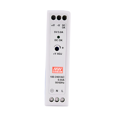
The MDR-20-5 is a compact and reliable DIN-rail-mounted power supply manufactured by Meanwell. It delivers a stable 5V DC output with a maximum current of 4A, making it suitable for a wide range of industrial and automation applications. Its robust design includes built-in protections against short circuits, overloads, and overvoltage, ensuring safe and efficient operation in demanding environments.

Explore Projects Built with Power Supply MDR-20-5

Use Cirkit Designer to design, explore, and prototype these projects online. Some projects support real-time simulation. Click "Open Project" to start designing instantly!
USB-Powered DC Gear Motor with LED Indicator
Image of Hand Crank mobile charger : A project utilizing Power Supply MDR-20-5 in a practical application
This circuit appears to be a power supply unit with a bridge rectifier connected to a DC gear motor, indicating it is designed to convert AC to DC power for the motor. An electrolytic capacitor is used for smoothing the DC output, and a 7805 voltage regulator is included to provide a stable 5V output. Additionally, there is an LED with a series resistor, likely serving as a power indicator light.
Cirkit Designer LogoOpen Project in Cirkit Designer
Dual 5V Power Supply Distribution Circuit with Toggle Switch Control
Image of rfdriver: A project utilizing Power Supply MDR-20-5 in a practical application
This circuit consists of two 5V 5A power supplies connected to an AC wall plug point, providing DC output through a 12-way connector. The ground connections from both power supplies are interconnected and also connected to the ground pins of two toggle switches. The DC outputs from the power supplies are separately connected to different pins on the 12-way connector, with each power supply output being switchable via one of the toggle switches.
Cirkit Designer LogoOpen Project in Cirkit Designer
Battery-Powered USB Charger with LED Indicator and DC Motor
Image of Copy of Hand Crank mobile charger : A project utilizing Power Supply MDR-20-5 in a practical application
This circuit converts AC power to DC using a bridge rectifier and regulates the voltage to 5V with a 7805 voltage regulator. It powers a USB port and indicates power status with an LED, while also providing a charging interface through a multi-charging cable.
Cirkit Designer LogoOpen Project in Cirkit Designer
12V to 5V Power Supply with LED Indicator and Push Switch
Image of Power Supply LVCO: A project utilizing Power Supply MDR-20-5 in a practical application
This circuit is a 12V to 5V regulated power supply with an LED indicator. It uses a 5408 diode for reverse polarity protection, an LM340T5 7805 voltage regulator to step down the voltage to 5V, and a push switch to control the LED indicator. The circuit also includes capacitors for filtering and a resistor to limit the current through the LED.
Cirkit Designer LogoOpen Project in Cirkit Designer

Explore Projects Built with Power Supply MDR-20-5

Use Cirkit Designer to design, explore, and prototype these projects online. Some projects support real-time simulation. Click "Open Project" to start designing instantly!
Image of Hand Crank mobile charger : A project utilizing Power Supply MDR-20-5 in a practical application
USB-Powered DC Gear Motor with LED Indicator
This circuit appears to be a power supply unit with a bridge rectifier connected to a DC gear motor, indicating it is designed to convert AC to DC power for the motor. An electrolytic capacitor is used for smoothing the DC output, and a 7805 voltage regulator is included to provide a stable 5V output. Additionally, there is an LED with a series resistor, likely serving as a power indicator light.
Cirkit Designer LogoOpen Project in Cirkit Designer
Image of rfdriver: A project utilizing Power Supply MDR-20-5 in a practical application
Dual 5V Power Supply Distribution Circuit with Toggle Switch Control
This circuit consists of two 5V 5A power supplies connected to an AC wall plug point, providing DC output through a 12-way connector. The ground connections from both power supplies are interconnected and also connected to the ground pins of two toggle switches. The DC outputs from the power supplies are separately connected to different pins on the 12-way connector, with each power supply output being switchable via one of the toggle switches.
Cirkit Designer LogoOpen Project in Cirkit Designer
Image of Copy of Hand Crank mobile charger : A project utilizing Power Supply MDR-20-5 in a practical application
Battery-Powered USB Charger with LED Indicator and DC Motor
This circuit converts AC power to DC using a bridge rectifier and regulates the voltage to 5V with a 7805 voltage regulator. It powers a USB port and indicates power status with an LED, while also providing a charging interface through a multi-charging cable.
Cirkit Designer LogoOpen Project in Cirkit Designer
Image of Power Supply LVCO: A project utilizing Power Supply MDR-20-5 in a practical application
12V to 5V Power Supply with LED Indicator and Push Switch
This circuit is a 12V to 5V regulated power supply with an LED indicator. It uses a 5408 diode for reverse polarity protection, an LM340T5 7805 voltage regulator to step down the voltage to 5V, and a push switch to control the LED indicator. The circuit also includes capacitors for filtering and a resistor to limit the current through the LED.
Cirkit Designer LogoOpen Project in Cirkit Designer

Common Applications

  • Industrial control systems
  • Factory automation equipment
  • IoT devices and embedded systems
  • LED lighting systems
  • Communication devices

Technical Specifications

Key Specifications

Parameter Value
Manufacturer Meanwell
Model Number MDR-20-5
Input Voltage Range 85-264 VAC / 120-370 VDC
Output Voltage 5V DC
Maximum Output Current 4A
Output Power 20W
Efficiency 78% (typical)
Operating Temperature -20°C to +70°C
Dimensions 22.5mm x 90mm x 100mm
Mounting Type DIN Rail
Protections Short-circuit, Overload,
Overvoltage
Certifications UL, CE, TUV, EAC, CB

Pin Configuration and Descriptions

The MDR-20-5 features screw terminal connections for input and output. Below is the pin configuration:

Pin Number Label Description
1 L AC Line Input
2 N AC Neutral Input
3 +V Positive DC Output (5V)
4 -V Negative DC Output (Ground)

Usage Instructions

How to Use the MDR-20-5 in a Circuit

  1. Mounting: Secure the MDR-20-5 onto a DIN rail in your control panel or enclosure.
  2. Input Connection:
    • Connect the AC line (L) and neutral (N) terminals to the appropriate AC power source.
    • Ensure the input voltage is within the specified range (85-264 VAC).
  3. Output Connection:
    • Connect the +V terminal to the positive rail of your circuit.
    • Connect the -V terminal to the ground rail of your circuit.
  4. Load Considerations:
    • Ensure the total load does not exceed the maximum output current of 4A.
    • Use appropriately rated wires for both input and output connections.
  5. Power On:
    • After verifying all connections, power on the AC source. The MDR-20-5 will provide a stable 5V DC output.

Important Considerations and Best Practices

  • Ventilation: Ensure adequate airflow around the power supply to prevent overheating.
  • Fuse Protection: Use an external fuse or circuit breaker on the input side for added safety.
  • Grounding: Properly ground the power supply to reduce electrical noise and improve safety.
  • Load Regulation: For optimal performance, maintain the load within 10-90% of the rated output.

Example: Connecting to an Arduino UNO

The MDR-20-5 can be used to power an Arduino UNO. Below is an example wiring and code snippet:

Wiring

  1. Connect the +V terminal of the MDR-20-5 to the 5V pin of the Arduino UNO.
  2. Connect the -V terminal of the MDR-20-5 to the GND pin of the Arduino UNO.

Code Example

// Example code to blink an LED using Arduino UNO powered by MDR-20-5

const int ledPin = 13; // Pin connected to the onboard LED

void setup() {
  pinMode(ledPin, OUTPUT); // Set the LED pin as an output
}

void loop() {
  digitalWrite(ledPin, HIGH); // Turn the LED on
  delay(1000);               // Wait for 1 second
  digitalWrite(ledPin, LOW);  // Turn the LED off
  delay(1000);               // Wait for 1 second
}

Troubleshooting and FAQs

Common Issues and Solutions

Issue Possible Cause Solution
No output voltage Incorrect input wiring Verify AC input connections (L and N).
Input voltage out of range Ensure input voltage is within 85-264 VAC.
Overload or short circuit on output Check and remove excessive load or shorts.
Output voltage fluctuates Insufficient ventilation Ensure proper airflow around the unit.
Load exceeds maximum rating Reduce the load to within 4A.
Power supply overheats High ambient temperature Operate within the specified temperature.
Poor ventilation Improve airflow or reposition the unit.

FAQs

  1. Can the MDR-20-5 be used with DC input?

    • Yes, it supports DC input in the range of 120-370 VDC.
  2. What happens if the load exceeds 4A?

    • The power supply will activate overload protection and shut down the output to prevent damage.
  3. Is the MDR-20-5 suitable for outdoor use?

    • No, it is designed for indoor use in a controlled environment.
  4. Can I use the MDR-20-5 to power multiple devices?

    • Yes, as long as the total current draw does not exceed 4A.

By following this documentation, users can safely and effectively integrate the MDR-20-5 into their projects and systems.