Cirkit Designer Logo
Cirkit Designer
Your all-in-one circuit design IDE
Home / 
Component Documentation

How to Use Raspberry Pi Pico: Examples, Pinouts, and Specs
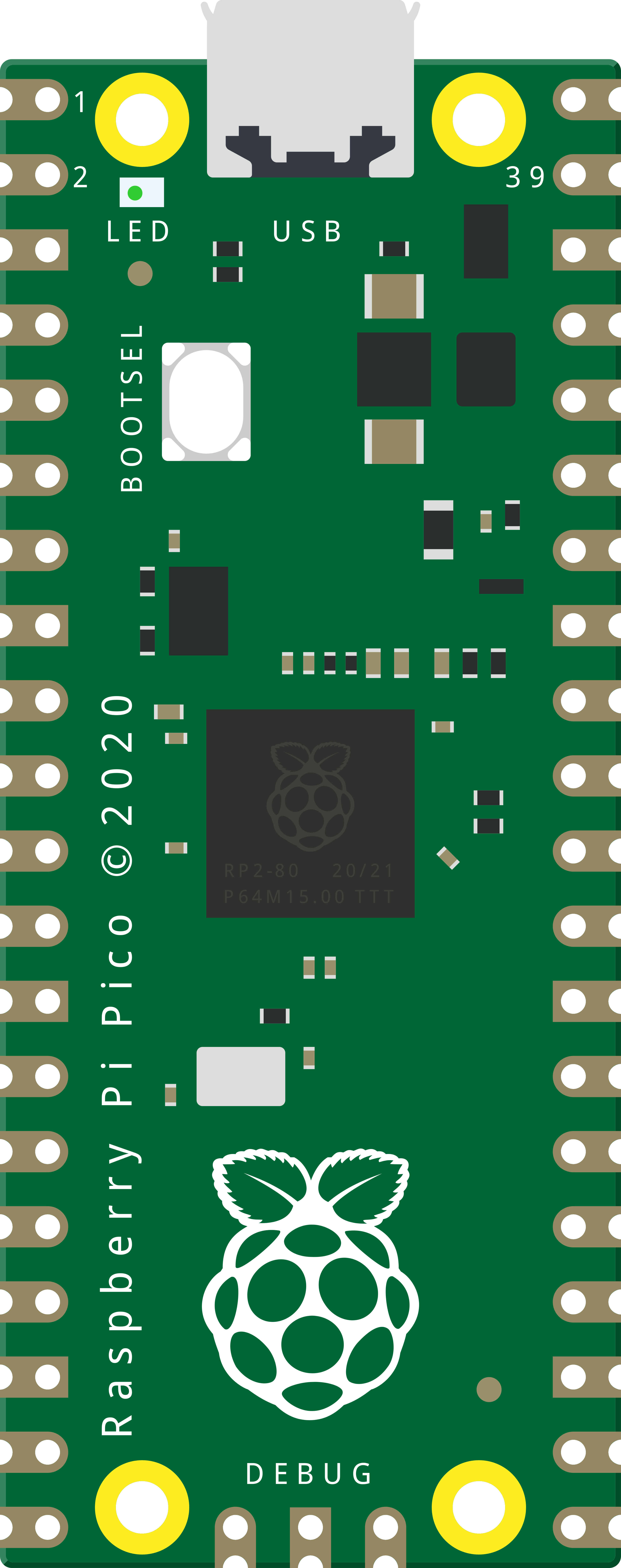

Image of Raspberry Pi Pico
Cirkit Designer LogoDesign with Raspberry Pi Pico in Cirkit Designer

Introduction

The Raspberry Pi Pico is a compact, low-cost microcontroller board built around the Raspberry Pi RP2040 chip. It features dual-core ARM Cortex-M0+ processors, 264KB of SRAM, and 2MB of onboard flash memory. Designed for versatility, the Pico is ideal for a wide range of applications, including IoT devices, robotics, home automation, and educational projects. Its GPIO pins allow seamless interfacing with sensors, actuators, and other peripherals, while its support for multiple programming languages, such as MicroPython and C/C++, makes it accessible to both beginners and experienced developers.

Explore Projects Built with Raspberry Pi Pico
Use Cirkit Designer to design, explore, and prototype these projects online. Some projects support real-time simulation. Click "Open Project" to start designing instantly!
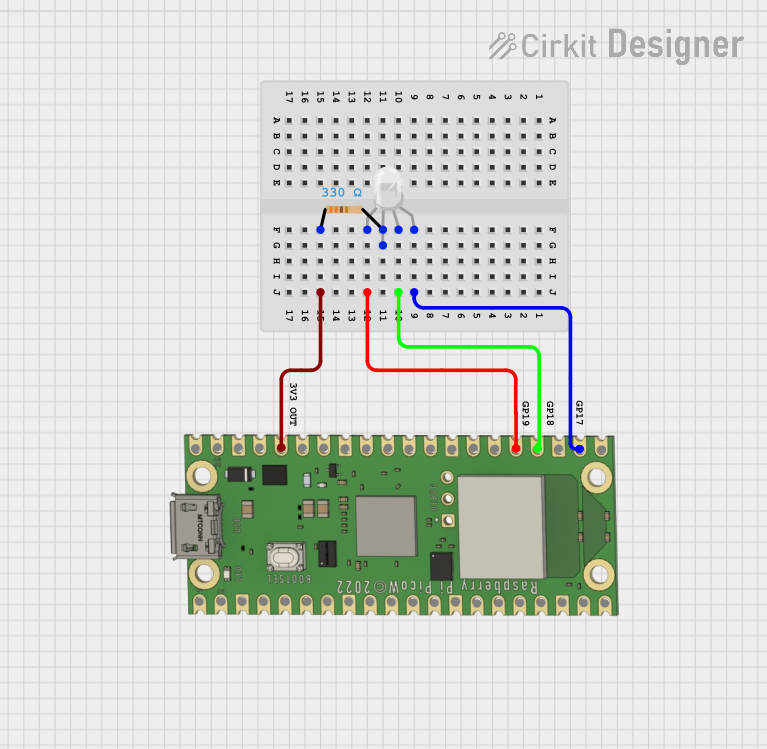
Wi-Fi Controlled RGB Lighting with Raspberry Pi Pico W
Image of Smart Home Automation 1: A project utilizing Raspberry Pi Pico in a practical application
This circuit features a Raspberry Pi Pico W microcontroller connected to an RGB LED through GPIO pins GP17, GP18, and GP19 for controlling the blue, green, and red channels, respectively. A resistor is connected between the 3V3 OUT pin of the Pico and the common cathode of the RGB LED to limit the current. The embedded code suggests the Pico W is configured for Wi-Fi connectivity and MQTT communication to control the LED and possibly other peripherals not shown in the circuit, with additional functionality for sensor monitoring and display output.
Cirkit Designer LogoOpen Project in Cirkit Designer
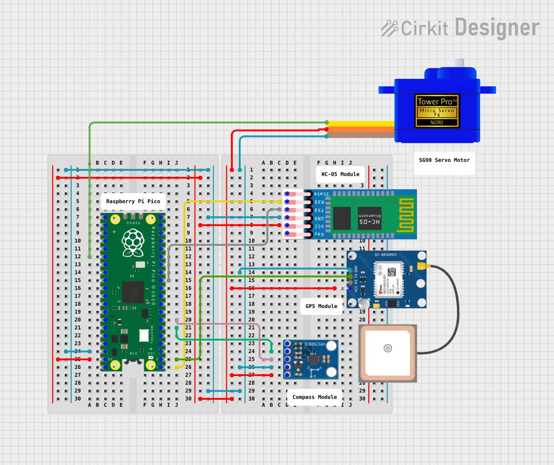
Raspberry Pi Pico-Based Navigation System with Bluetooth and GPS
Image of sat_dish: pwm application: A project utilizing Raspberry Pi Pico in a practical application
This circuit features a Raspberry Pi Pico microcontroller interfaced with multiple peripherals for navigation and control. It includes an HC-05 Bluetooth module for wireless communication, an HMC5883L compass for magnetic heading detection, a GPS NEO 6M module for location tracking, and an SG90 servomotor for actuation. The Pico manages data exchange with the GPS and compass via serial connections, controls the servomotor, and communicates wirelessly through the HC-05 module.
Cirkit Designer LogoOpen Project in Cirkit Designer
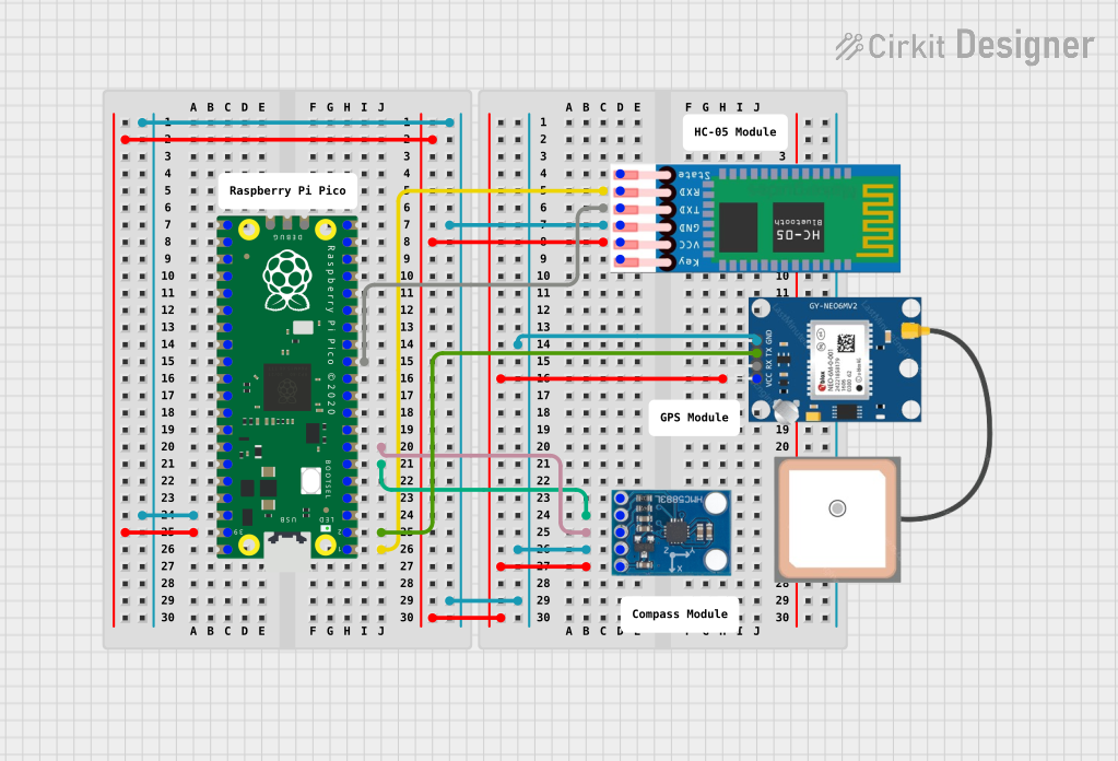
Raspberry Pi Pico-Based Navigation Assistant with Bluetooth and GPS
Image of sat_dish: compass example: A project utilizing Raspberry Pi Pico in a practical application
This circuit features a Raspberry Pi Pico microcontroller interfaced with an HC-05 Bluetooth module for wireless communication, an HMC5883L compass module for magnetic field measurement, and a GPS NEO 6M module for location tracking. The Pico is configured to communicate with the HC-05 via serial connection (TX/RX), with the compass module via I2C (SCL/SDA), and with the GPS module via serial (TX/RX). Common power (VCC) and ground (GND) lines are shared among all modules, indicating a unified power system.
Cirkit Designer LogoOpen Project in Cirkit Designer
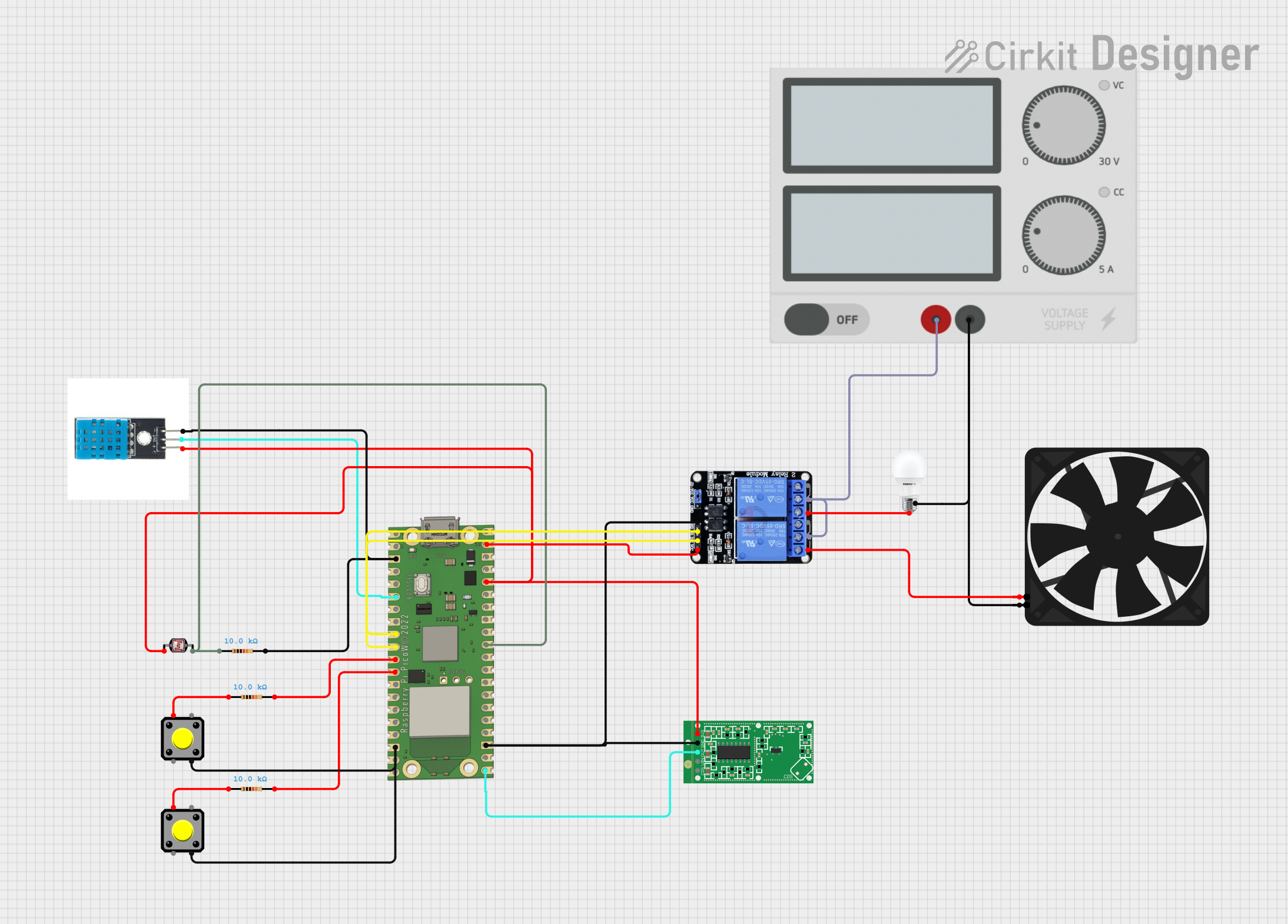
Raspberry Pi Pico W-Based Smart Home Automation System with Motion Detection and Environmental Monitoring
Image of Smart Home Automation 1: A project utilizing Raspberry Pi Pico in a practical application
This circuit features a Raspberry Pi Pico W microcontroller connected to various sensors and actuators, including a DHT11 temperature and humidity sensor, an RCWL-0516 microwave radar motion sensor, a photocell (LDR) with a resistor for light detection, and a two-channel relay controlling a bulb and a fan. The microcontroller runs code to monitor environmental conditions and motion, displaying information on an LCD and allowing remote control via MQTT messages over Wi-Fi. It supports both automatic sensor-based operation and remote app control, with pushbuttons to switch between modes.
Cirkit Designer LogoOpen Project in Cirkit Designer

Explore Projects Built with Raspberry Pi Pico

Use Cirkit Designer to design, explore, and prototype these projects online. Some projects support real-time simulation. Click "Open Project" to start designing instantly!
Image of Smart Home Automation 1: A project utilizing Raspberry Pi Pico in a practical application
Wi-Fi Controlled RGB Lighting with Raspberry Pi Pico W
This circuit features a Raspberry Pi Pico W microcontroller connected to an RGB LED through GPIO pins GP17, GP18, and GP19 for controlling the blue, green, and red channels, respectively. A resistor is connected between the 3V3 OUT pin of the Pico and the common cathode of the RGB LED to limit the current. The embedded code suggests the Pico W is configured for Wi-Fi connectivity and MQTT communication to control the LED and possibly other peripherals not shown in the circuit, with additional functionality for sensor monitoring and display output.
Cirkit Designer LogoOpen Project in Cirkit Designer
Image of sat_dish: pwm application: A project utilizing Raspberry Pi Pico in a practical application
Raspberry Pi Pico-Based Navigation System with Bluetooth and GPS
This circuit features a Raspberry Pi Pico microcontroller interfaced with multiple peripherals for navigation and control. It includes an HC-05 Bluetooth module for wireless communication, an HMC5883L compass for magnetic heading detection, a GPS NEO 6M module for location tracking, and an SG90 servomotor for actuation. The Pico manages data exchange with the GPS and compass via serial connections, controls the servomotor, and communicates wirelessly through the HC-05 module.
Cirkit Designer LogoOpen Project in Cirkit Designer
Image of sat_dish: compass example: A project utilizing Raspberry Pi Pico in a practical application
Raspberry Pi Pico-Based Navigation Assistant with Bluetooth and GPS
This circuit features a Raspberry Pi Pico microcontroller interfaced with an HC-05 Bluetooth module for wireless communication, an HMC5883L compass module for magnetic field measurement, and a GPS NEO 6M module for location tracking. The Pico is configured to communicate with the HC-05 via serial connection (TX/RX), with the compass module via I2C (SCL/SDA), and with the GPS module via serial (TX/RX). Common power (VCC) and ground (GND) lines are shared among all modules, indicating a unified power system.
Cirkit Designer LogoOpen Project in Cirkit Designer
Image of Smart Home Automation 1: A project utilizing Raspberry Pi Pico in a practical application
Raspberry Pi Pico W-Based Smart Home Automation System with Motion Detection and Environmental Monitoring
This circuit features a Raspberry Pi Pico W microcontroller connected to various sensors and actuators, including a DHT11 temperature and humidity sensor, an RCWL-0516 microwave radar motion sensor, a photocell (LDR) with a resistor for light detection, and a two-channel relay controlling a bulb and a fan. The microcontroller runs code to monitor environmental conditions and motion, displaying information on an LCD and allowing remote control via MQTT messages over Wi-Fi. It supports both automatic sensor-based operation and remote app control, with pushbuttons to switch between modes.
Cirkit Designer LogoOpen Project in Cirkit Designer

Technical Specifications

  • Microcontroller: Raspberry Pi RP2040
  • Processor: Dual-core ARM Cortex-M0+ @ 133 MHz
  • Memory: 264KB SRAM, 2MB onboard QSPI flash
  • GPIO Pins: 26 multi-function pins (3.3V logic level)
  • Communication Protocols: I2C, SPI, UART, PWM, ADC
  • Power Supply: 1.8V to 5.5V (via micro-USB or VSYS pin)
  • Operating Temperature: -20°C to +85°C
  • Dimensions: 51mm x 21mm x 1mm

Pin Configuration and Descriptions

The Raspberry Pi Pico has 40 pins, including power, ground, and GPIO pins. Below is a summary of the pin configuration:

Pin Number Pin Name Description
1 GP0 GPIO Pin 0, supports I2C0 SDA
2 GP1 GPIO Pin 1, supports I2C0 SCL
3 GND Ground
4 GP2 GPIO Pin 2, supports UART1 TX
5 GP3 GPIO Pin 3, supports UART1 RX
6 GND Ground
7 GP4 GPIO Pin 4, supports PWM
8 GP5 GPIO Pin 5, supports PWM
9 GND Ground
10 GP6 GPIO Pin 6, supports SPI0 RX
... ... ... (Refer to the official datasheet)
39 3V3(OUT) 3.3V Output
40 GND Ground

For the full pinout, refer to the official Raspberry Pi Pico documentation.

Usage Instructions

How to Use the Raspberry Pi Pico in a Circuit

  1. Powering the Pico:

    • Connect the Pico to a computer or power source via the micro-USB port.
    • Alternatively, supply power through the VSYS pin (1.8V to 5.5V).
  2. Programming the Pico:

    • Install MicroPython or C/C++ SDK on your computer.
    • Hold the BOOTSEL button while connecting the Pico to your computer to enter USB mass storage mode.
    • Drag and drop the firmware file (e.g., MicroPython .uf2 file) onto the Pico's storage.
  3. Connecting Peripherals:

    • Use the GPIO pins to interface with sensors, actuators, or other devices.
    • Ensure that all connected devices operate at 3.3V logic levels to avoid damage.

Example: Blinking an LED with MicroPython

Below is an example of how to blink an LED connected to GPIO pin 15 using MicroPython:


Import the Pin and Timer classes from the machine module

from machine import Pin, Timer

Configure GPIO15 as an output pin

led = Pin(15, Pin.OUT)

Define a function to toggle the LED state

def toggle_led(timer): led.toggle() # Toggle the LED on/off

Create a timer to call the toggle_led function every 500ms

timer = Timer() timer.init(freq=2, mode=Timer.PERIODIC, callback=toggle_led)


Important Considerations and Best Practices

  • Always use a level shifter when interfacing with 5V devices to protect the Pico's GPIO pins.
  • Avoid drawing excessive current from the 3.3V output pin (maximum 300mA).
  • Use decoupling capacitors when connecting external components to reduce noise and improve stability.

Troubleshooting and FAQs

Common Issues and Solutions

  1. Pico Not Detected by Computer:

    • Ensure the BOOTSEL button is held down while connecting the Pico to the computer.
    • Check the USB cable; some cables only support charging and not data transfer.
  2. Program Not Running After Power Cycle:

    • Ensure the program is saved to the Pico's flash memory.
    • Use the .uf2 file format for firmware updates.
  3. GPIO Pins Not Responding:

    • Verify that the connected device operates at 3.3V logic levels.
    • Check for loose connections or incorrect wiring.

FAQs

  • Can I power the Pico with a battery?
    Yes, you can power the Pico using a battery connected to the VSYS pin, as long as the voltage is between 1.8V and 5.5V.

  • What programming languages are supported?
    The Pico supports MicroPython, C/C++, and other languages via third-party tools.

  • How do I reset the Pico?
    Disconnect and reconnect the power, or press the reset button if available on your setup.

For more detailed information, refer to the official Raspberry Pi Pico documentation.