How to Use Arduino Giga R1 WiFi: Examples, Pinouts, and Specs
Introduction
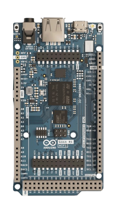
The Arduino Giga R1 WiFi is a powerful microcontroller board designed by Arduino for advanced IoT (Internet of Things) applications. It features built-in WiFi and Bluetooth connectivity, making it ideal for projects requiring wireless communication. With its high-performance processor, extensive I/O pins, and compatibility with a wide range of sensors and modules, the Giga R1 WiFi is suitable for both hobbyists and professionals.
Explore Projects Built with Arduino Giga R1 WiFi
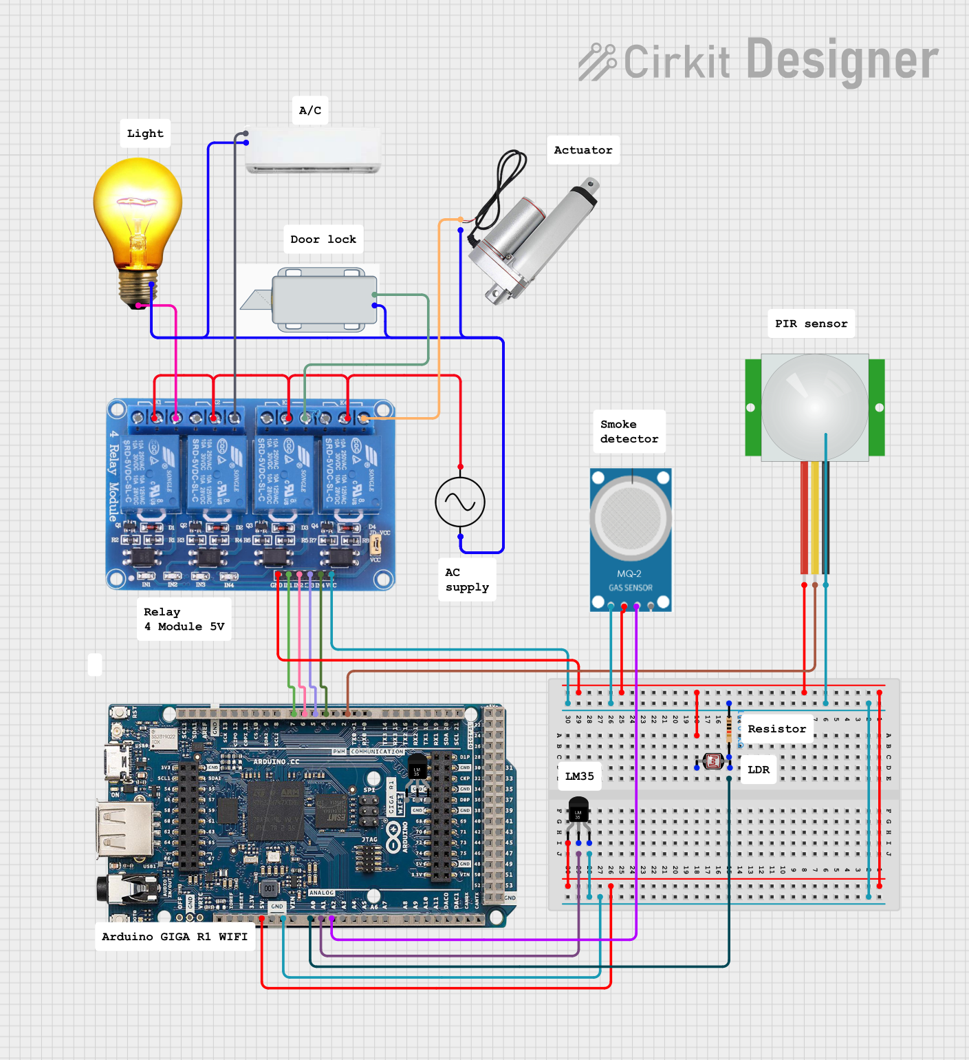
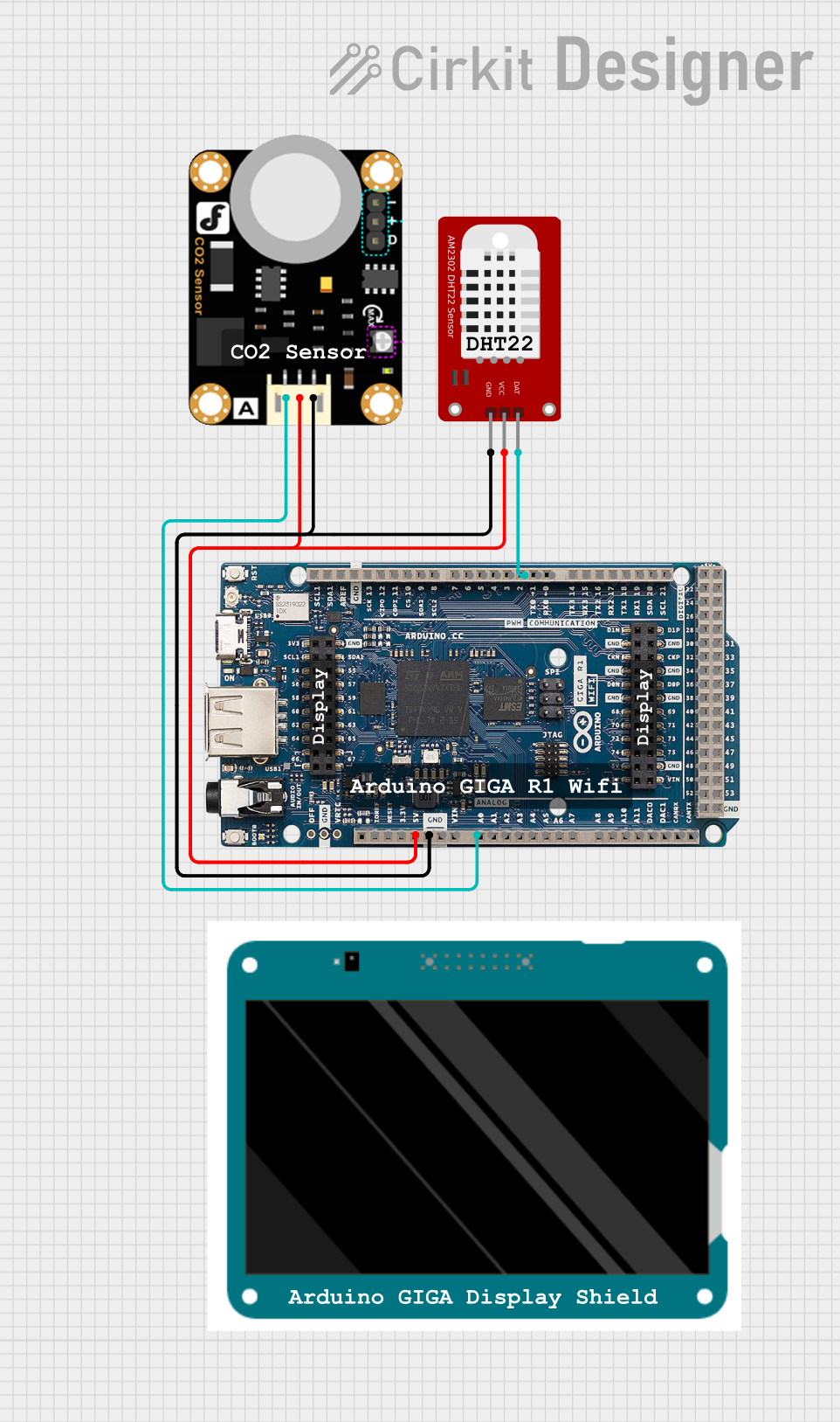
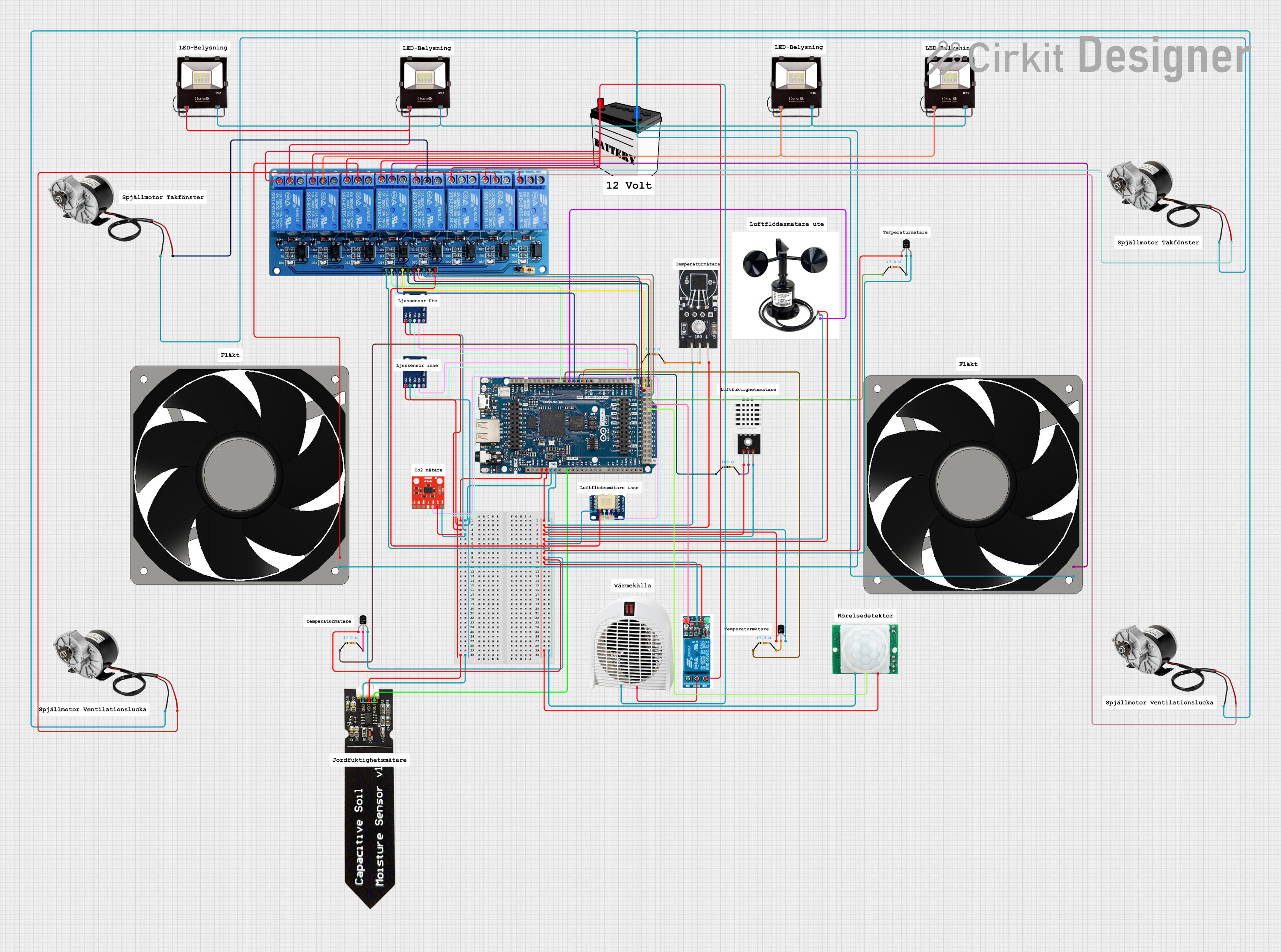
Explore Projects Built with Arduino Giga R1 WiFi
Common Applications and Use Cases
- IoT devices and smart home automation
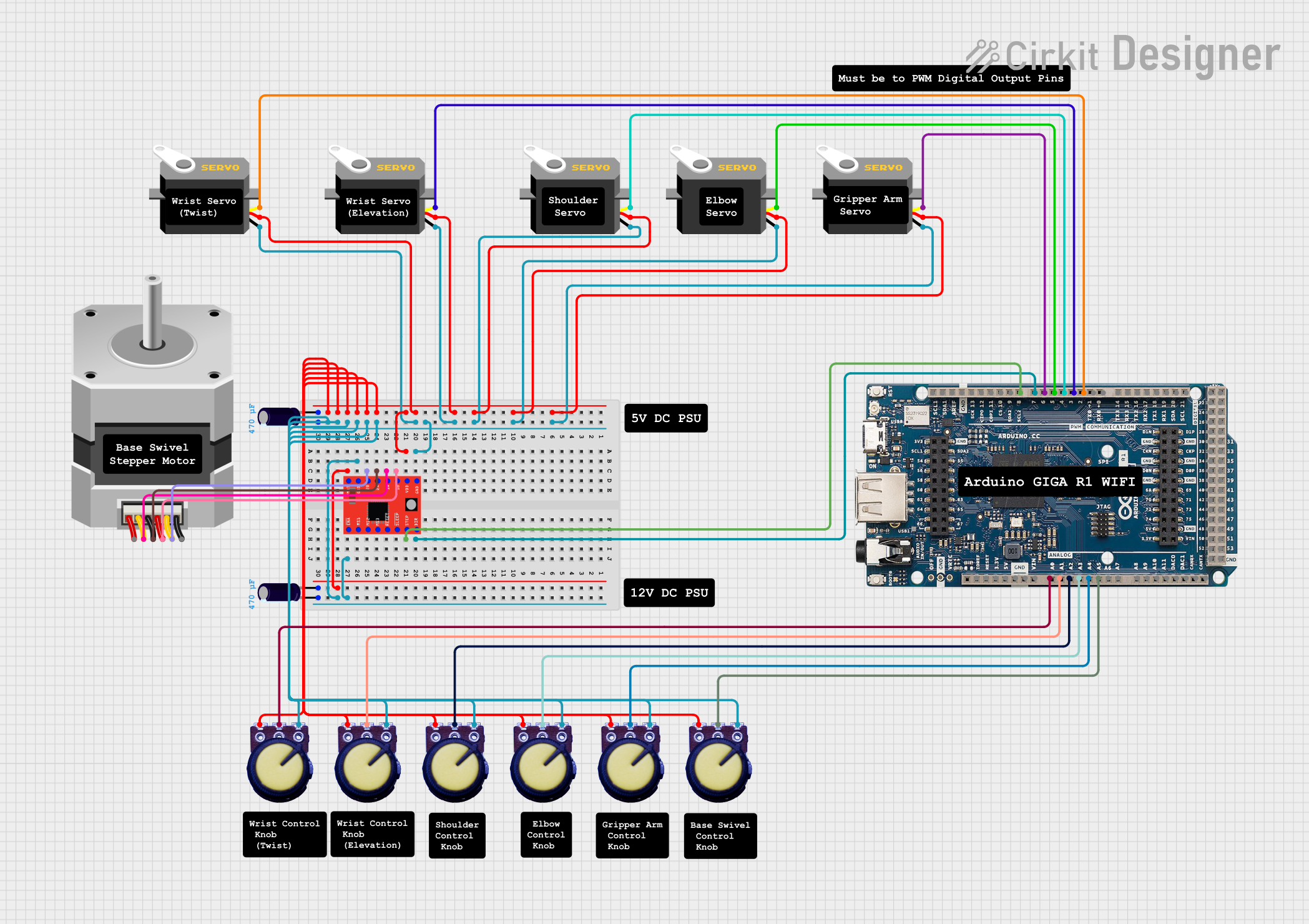
- Robotics and motor control
- Data logging and environmental monitoring
- Wireless communication and networking
- Prototyping advanced embedded systems
Technical Specifications
The following table outlines the key technical details of the Arduino Giga R1 WiFi:
| Specification | Details |
|---|---|
| Microcontroller | STM32H747 dual-core (Cortex-M7 @ 480 MHz and Cortex-M4 @ 240 MHz) |
| Operating Voltage | 3.3V |
| Input Voltage (VIN) | 7-12V |
| Digital I/O Pins | 76 (12 of which support PWM) |
| Analog Input Pins | 12 |
| Analog Output Pins | 2 (DAC) |
| Flash Memory | 8 MB |
| SRAM | 1 MB |
| WiFi and Bluetooth | Integrated (based on Murata 1DX module) |
| USB Ports | USB-C (for programming and power) and USB-A (host functionality) |
| Communication Protocols | UART, I2C, SPI, CAN, Ethernet |
| Operating Temperature | -40°C to 85°C |
| Dimensions | 102 x 25 mm |
Pin Configuration and Descriptions
The Arduino Giga R1 WiFi has a rich set of pins for various functionalities. Below is a summary of the pin configuration:
| Pin | Function | Description |
|---|---|---|
| VIN | Power Input | External power supply input (7-12V). |
| 3.3V | Power Output | Regulated 3.3V output for powering external components. |
| GND | Ground | Common ground for the circuit. |
| Digital Pins | D0-D75 | General-purpose digital I/O pins (PWM supported on select pins). |
| Analog Pins | A0-A11 | Analog input pins for reading sensor data. |
| DAC0, DAC1 | Analog Output | Digital-to-analog converter pins for generating analog signals. |
| I2C | SDA, SCL | I2C communication pins for connecting sensors and modules. |
| SPI | SCK, MISO, MOSI, SS | SPI communication pins for high-speed data transfer. |
| UART | TX, RX | Serial communication pins for debugging or connecting peripherals. |
| CAN | CAN_H, CAN_L | Controller Area Network pins for automotive and industrial applications. |
| USB-C | USB Data/Power | Used for programming, debugging, and powering the board. |
| USB-A | USB Host | Allows the board to act as a USB host for peripherals like keyboards or mice. |
Usage Instructions
How to Use the Arduino Giga R1 WiFi in a Circuit
Powering the Board:
- Use the USB-C port to power the board via a computer or USB adapter.
- Alternatively, connect an external power supply (7-12V) to the VIN pin.
Connecting Components:
- Use the digital and analog pins to connect sensors, actuators, and other peripherals.
- For wireless communication, configure the built-in WiFi or Bluetooth module.
Programming the Board:
- Install the Arduino IDE (version 2.0 or later) on your computer.
- Select "Arduino Giga R1 WiFi" as the board in the IDE.
- Connect the board to your computer via USB-C and upload your code.
Using Communication Protocols:
- Use I2C, SPI, or UART pins to interface with external modules.
- For CAN communication, connect the CAN_H and CAN_L pins to the CAN bus.
Important Considerations and Best Practices
- Ensure the board is powered within the recommended voltage range to avoid damage.
- Use level shifters when interfacing 5V components with the 3.3V pins.
- Avoid drawing excessive current from the 3.3V pin to prevent overheating.
- Use proper pull-up resistors for I2C communication.
- When using WiFi or Bluetooth, ensure the antenna area is unobstructed for optimal signal strength.
Example Code for WiFi Connection
Below is an example of how to connect the Arduino Giga R1 WiFi to a WiFi network and send data to a server:
#include <WiFi.h> // Include the WiFi library

const char* ssid = "Your_SSID";       // Replace with your WiFi network name
const char* password = "Your_Password"; // Replace with your WiFi password
const char* server = "http://example.com"; // Replace with your server URL

void setup() {
  Serial.begin(115200); // Initialize serial communication
  delay(1000);          // Wait for serial monitor to open

  // Connect to WiFi
  Serial.print("Connecting to WiFi...");
  WiFi.begin(ssid, password);

  while (WiFi.status() != WL_CONNECTED) {
    delay(500);
    Serial.print(".");
  }
  Serial.println("\nWiFi connected!");
  Serial.print("IP Address: ");
  Serial.println(WiFi.localIP());
}

void loop() {
  // Example: Send a GET request to the server
  WiFiClient client;
  if (client.connect(server, 80)) {
    client.println("GET / HTTP/1.1");
    client.println("Host: example.com");
    client.println("Connection: close");
    client.println();
  }

  // Wait before sending the next request
  delay(10000);
}
Troubleshooting and FAQs
Common Issues and Solutions
The board is not detected by the Arduino IDE:
- Ensure the correct board ("Arduino Giga R1 WiFi") is selected in the IDE.
- Check the USB cable and port connection. Use a data-capable USB cable.
WiFi connection fails:
- Verify the SSID and password are correct.
- Ensure the WiFi network is within range and not overloaded.
Overheating issues:
- Avoid drawing excessive current from the 3.3V pin.
- Ensure proper ventilation around the board.
Code upload fails:
- Press the reset button on the board and try uploading again.
- Check for conflicting processes using the USB port (e.g., serial monitor).
FAQs
Can I use 5V sensors with the Giga R1 WiFi?
Yes, but you need to use level shifters to convert 5V signals to 3.3V.Does the board support OTA (Over-The-Air) updates?
Yes, the built-in WiFi module supports OTA updates with proper configuration.What is the maximum current output of the 3.3V pin?
The 3.3V pin can supply up to 800 mA, but it is recommended to stay below 500 mA for safety.Can I use the USB-A port for data transfer?
Yes, the USB-A port allows the board to act as a USB host for peripherals like keyboards, mice, or USB drives.