How to Use max7219: Examples, Pinouts, and Specs
Introduction
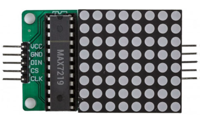
The MAX7219 is a compact, serial input/output common-cathode display driver designed to control up to 64 individual LEDs or 8 seven-segment displays. It simplifies the process of driving multiple LEDs by requiring only three microcontroller pins for communication (DATA, CLOCK, and LOAD). Additionally, the MAX7219 supports cascading, enabling multiple devices to be connected in series for larger display configurations.
Explore Projects Built with max7219

Explore Projects Built with max7219
Common Applications
- Driving 7-segment numeric displays
- LED matrix displays (e.g., 8x8 LED grids)
- Digital clocks, counters, and thermometers
- Message boards and scrolling text displays
- Any application requiring efficient control of multiple LEDs
Technical Specifications
The MAX7219 is a versatile and efficient display driver with the following key specifications:
| Parameter | Value |
|---|---|
| Operating Voltage (Vcc) | 4.0V to 5.5V |
| Maximum Supply Current | 330mA (all LEDs on) |
| Data Communication | Serial (SPI-compatible) |
| Maximum Clock Frequency | 10 MHz |
| LED Drive Capability | Up to 64 individual LEDs |
| Display Types Supported | 7-segment displays, LED matrices |
| Operating Temperature | -40°C to +85°C |
Pin Configuration and Descriptions
The MAX7219 comes in a 24-pin DIP or SO package. Below is the pinout and description:
| Pin | Name | Description |
|---|---|---|
| 1 | DIG 0 | Digit 0 (Segment driver for digit 0 or row 0 in LED matrix) |
| 2–8 | DIG 1–7 | Digit 1 to Digit 7 (Segment drivers for digits 1–7 or rows 1–7 in LED matrix) |
| 9 | GND | Ground (0V reference) |
| 10 | DOUT | Serial data output for cascading multiple MAX7219 devices |
| 11 | LOAD/CS | Chip select (active low) |
| 12 | CLK | Serial clock input |
| 13 | DIN | Serial data input |
| 14 | VCC | Positive supply voltage (4.0V to 5.5V) |
| 15–23 | SEG DP–A | Segment drivers for decimal point (DP) and segments A–G |
| 24 | ISET | Current setting resistor pin (connect to a resistor to set LED current) |
Usage Instructions
How to Use the MAX7219 in a Circuit
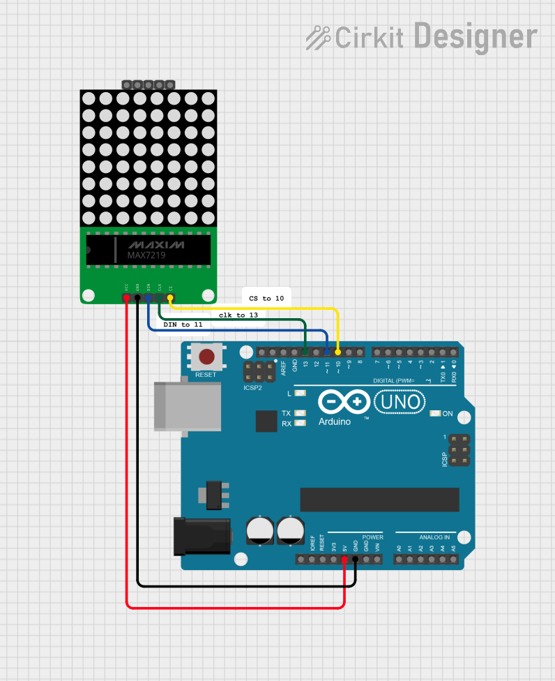
- Power Supply: Connect the VCC pin to a 5V power source and the GND pin to ground.
- Current Setting Resistor: Attach a resistor (typically 10kΩ) between the ISET pin and GND to set the LED current.
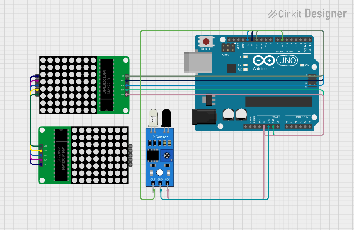
- Data Communication: Connect the DIN, CLK, and LOAD/CS pins to the microcontroller's SPI-compatible pins.
- LED/Display Connections: Attach the LED matrix or 7-segment displays to the DIG and SEG pins as per your design.
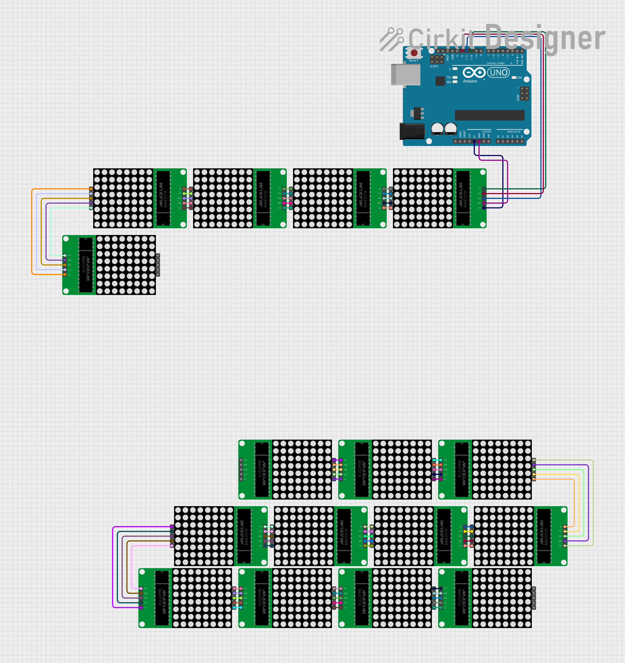
- Cascading: To cascade multiple MAX7219 devices, connect the DOUT pin of the first device to the DIN pin of the next device.
Important Considerations
- Bypass Capacitor: Place a 10µF electrolytic capacitor and a 0.1µF ceramic capacitor across VCC and GND for noise suppression.
- Segment Current: Ensure the ISET resistor value is chosen to limit the segment current to safe levels (typically 40mA max per segment).
- Cascading: When cascading, ensure the clock signal is strong enough to drive all devices in the chain.
Example: Using MAX7219 with Arduino UNO
Below is an example of how to control an 8x8 LED matrix using the MAX7219 and Arduino UNO:
#include <LedControl.h> // Include the LedControl library

// Initialize the LedControl object
// Parameters: DIN pin, CLK pin, LOAD/CS pin, number of MAX7219 devices
LedControl lc = LedControl(12, 11, 10, 1);

void setup() {
  // Initialize the MAX7219
  lc.shutdown(0, false); // Wake up the MAX7219
  lc.setIntensity(0, 8); // Set brightness level (0-15)
  lc.clearDisplay(0);    // Clear the display
}

void loop() {
  // Display a simple pattern on the 8x8 LED matrix
  for (int row = 0; row < 8; row++) {
    lc.setRow(0, row, 0b10101010); // Alternating pattern
    delay(200); // Wait for 200ms
  }
}
Best Practices
- Use the LedControl library for Arduino to simplify communication with the MAX7219.
- Avoid exceeding the maximum current rating of the device by properly calculating the ISET resistor value.
- For larger cascaded setups, ensure proper power distribution and decoupling capacitors for each MAX7219.
Troubleshooting and FAQs
Common Issues
No Output on LEDs/Display:
- Verify the wiring connections, especially DIN, CLK, and LOAD/CS.
- Ensure the ISET resistor is properly connected and has the correct value.
- Check the power supply voltage (4.0V to 5.5V).
Flickering LEDs:
- Add bypass capacitors (10µF and 0.1µF) across VCC and GND.
- Ensure the microcontroller's SPI clock frequency is within the MAX7219's limits.
Cascaded Devices Not Working:
- Verify the DOUT of one device is connected to the DIN of the next.
- Ensure the LOAD/CS signal is properly synchronized for all devices.
FAQs
Q: Can I use the MAX7219 with a 3.3V microcontroller?
A: The MAX7219 requires a minimum VCC of 4.0V. However, you can use level shifters to interface a 3.3V microcontroller with the MAX7219.
Q: How many MAX7219 devices can I cascade?
A: Theoretically, you can cascade as many devices as needed, but practical limitations like signal integrity and power supply constraints may arise after 8–10 devices.
Q: How do I adjust the brightness of the LEDs?
A: Use the setIntensity() function in the LedControl library or send the appropriate command via SPI to adjust brightness (0–15 levels).
By following this documentation, you can effectively integrate the MAX7219 into your projects and troubleshoot common issues with ease.