How to Use Relay Add-on Module for Seeed Studio XIAO and QT Py: Examples, Pinouts, and Specs
Introduction
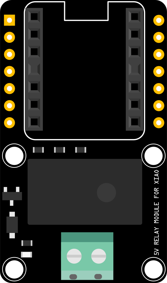
The Relay Add-on Module is a compact and efficient solution for controlling high-voltage devices using low-voltage signals. Designed specifically for Seeed Studio's XIAO and Adafruit's QT Py microcontrollers, this module simplifies the process of integrating relays into your projects. It allows microcontrollers to safely switch high-power devices such as lights, fans, or motors, making it ideal for home automation, IoT applications, and prototyping.
Explore Projects Built with Relay Add-on Module for Seeed Studio XIAO and QT Py


Explore Projects Built with Relay Add-on Module for Seeed Studio XIAO and QT Py
Common Applications and Use Cases
- Home Automation: Control appliances like lights, fans, or heaters.
- IoT Projects: Enable remote control of high-power devices via the internet.
- Prototyping: Quickly test and implement relay-based circuits.
- Industrial Automation: Manage high-voltage equipment with microcontroller precision.
Technical Specifications
Key Technical Details
- Operating Voltage: 3.3V or 5V (compatible with XIAO and QT Py logic levels)
- Relay Voltage: Supports up to 250V AC or 30V DC
- Relay Current: Maximum 10A
- Trigger Current: < 20mA
- Dimensions: Compact form factor to fit seamlessly with XIAO and QT Py
- Interface: Standard pin headers for direct connection to microcontrollers
- Indicator: Onboard LED to indicate relay activation
Pin Configuration and Descriptions
The Relay Add-on Module has a simple pinout for easy integration:
| Pin Name | Description |
|---|---|
| VCC | Power input (3.3V or 5V, depending on the microcontroller used). |
| GND | Ground connection. |
| IN | Signal input pin to trigger the relay (active HIGH). |
| COM | Common terminal of the relay switch. |
| NO | Normally Open terminal (connected to COM when the relay is activated). |
| NC | Normally Closed terminal (connected to COM when the relay is not activated). |
Usage Instructions
How to Use the Component in a Circuit
Connect the Module to the Microcontroller:
- Attach the VCC and GND pins of the module to the corresponding power and ground pins of the XIAO or QT Py.
- Connect the IN pin to a GPIO pin on the microcontroller.
Connect the High-Voltage Device:
- Wire the high-voltage device to the relay terminals (COM, NO, or NC) based on your desired switching behavior:
- Use COM and NO for devices that should turn ON when the relay is activated.
- Use COM and NC for devices that should turn OFF when the relay is activated.
- Wire the high-voltage device to the relay terminals (COM, NO, or NC) based on your desired switching behavior:
Write the Control Code:
- Use the microcontroller to send a HIGH signal to the IN pin to activate the relay.
Power the Circuit:
- Ensure the microcontroller and relay module are powered appropriately. Double-check all connections before applying power.
Important Considerations and Best Practices
- Isolation: Ensure proper isolation between the low-voltage control side and the high-voltage load side to prevent damage or hazards.
- Current Ratings: Do not exceed the relay's maximum current rating (10A) to avoid overheating or failure.
- Flyback Diode: The module includes a built-in flyback diode to protect the microcontroller from voltage spikes caused by the relay coil.
- Signal Voltage: Verify that the microcontroller's GPIO pin can provide the required signal voltage (3.3V or 5V) to trigger the relay.
Example Code for Arduino UNO
Below is an example code snippet to control the relay module using an Arduino-compatible board like the Seeed Studio XIAO:
// Define the GPIO pin connected to the relay module's IN pin
const int relayPin = 7;

void setup() {
  // Set the relay pin as an output
  pinMode(relayPin, OUTPUT);

  // Ensure the relay is off at startup
  digitalWrite(relayPin, LOW);
}

void loop() {
  // Turn the relay ON
  digitalWrite(relayPin, HIGH);
  delay(5000); // Keep the relay on for 5 seconds

  // Turn the relay OFF
  digitalWrite(relayPin, LOW);
  delay(5000); // Keep the relay off for 5 seconds
}
Notes on the Code
- Replace
7with the GPIO pin number you are using to connect to the relay's IN pin. - Adjust the
delay()values to change the ON/OFF timing.
Troubleshooting and FAQs
Common Issues and Solutions
Relay Not Activating:
- Cause: Insufficient signal voltage or current from the microcontroller.
- Solution: Verify that the GPIO pin is set to HIGH and can provide the required voltage (3.3V or 5V).
High-Voltage Device Not Switching:
- Cause: Incorrect wiring of the relay terminals (COM, NO, NC).
- Solution: Double-check the wiring and ensure the device is connected to the correct terminals.
Module Overheating:
- Cause: Exceeding the relay's current rating (10A).
- Solution: Use a device with a current draw within the relay's specifications.
Microcontroller Resets When Relay Activates:
- Cause: Voltage spikes or insufficient power supply.
- Solution: Ensure the power supply can handle the relay's activation current. Use decoupling capacitors if necessary.
FAQs
Can I use this module with a 3.3V microcontroller? Yes, the module is compatible with both 3.3V and 5V logic levels.
Is the relay module safe for high-voltage applications? Yes, but ensure proper isolation and follow safety guidelines when working with high voltages.
Can I control multiple relays with one microcontroller? Yes, as long as you have enough GPIO pins and the microcontroller can handle the combined current draw.
Does the module include a flyback diode? Yes, the module has a built-in flyback diode to protect the microcontroller from voltage spikes.
By following this documentation, you can effectively integrate the Relay Add-on Module into your projects and safely control high-voltage devices with ease.