How to Use NPK Soil Sensor: Examples, Pinouts, and Specs
Introduction
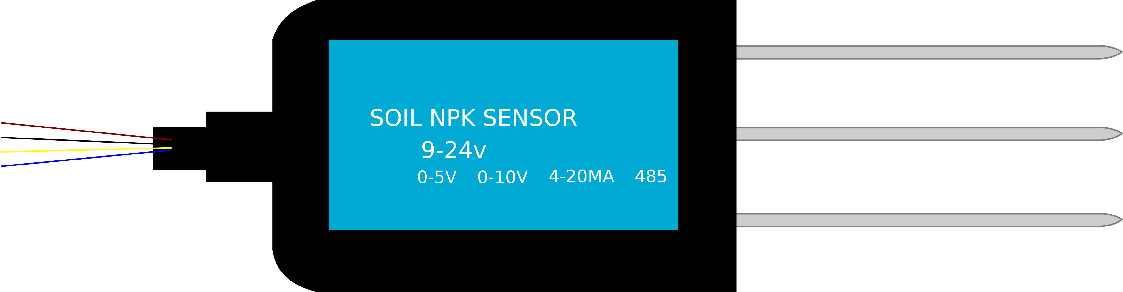
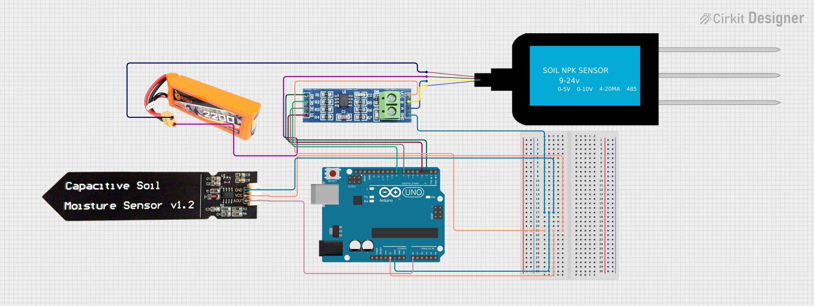
The NPK Soil Sensor is an innovative electronic device designed to measure the levels of Nitrogen (N), Phosphorus (P), and Potassium (K) in soil. These three nutrients are essential for plant growth and their balanced presence is crucial for agricultural success. The sensor is widely used by farmers, researchers, and hobbyists to monitor and optimize soil conditions, ensuring healthy crop yields.
Explore Projects Built with NPK Soil Sensor
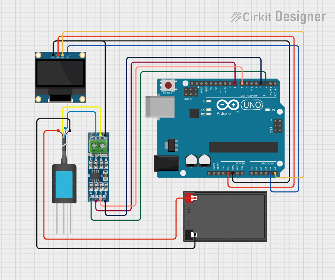
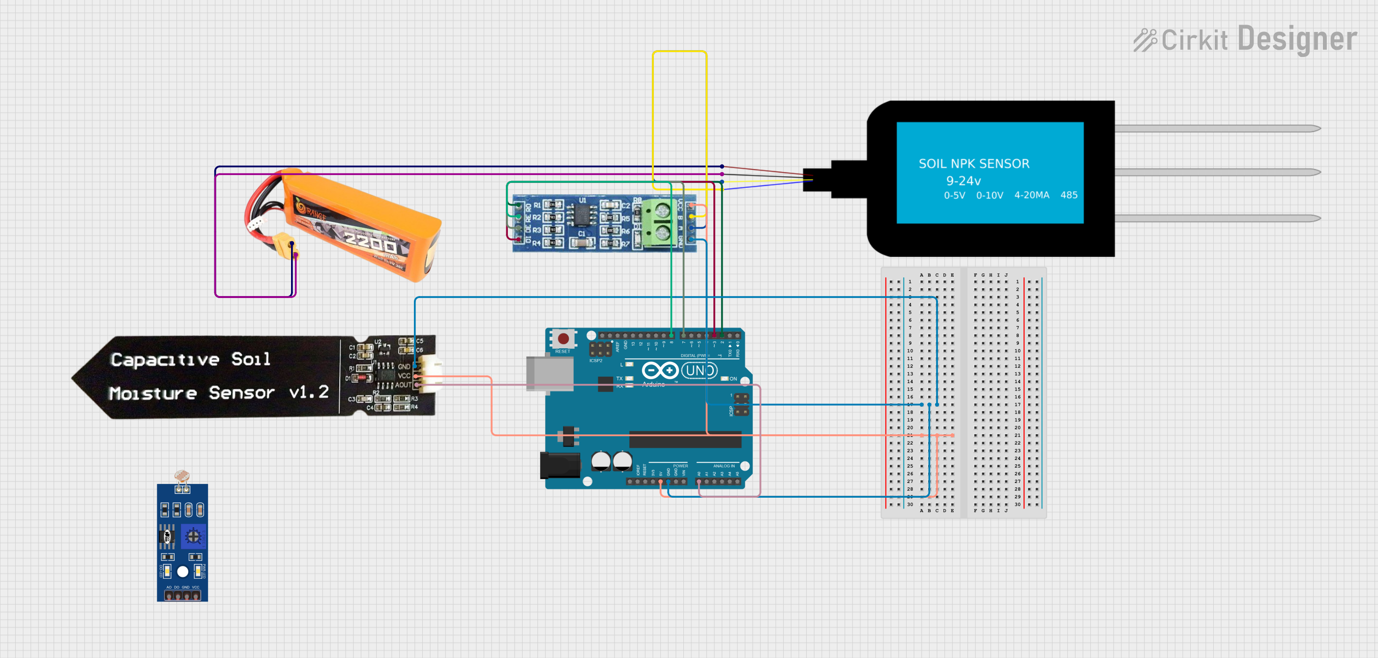
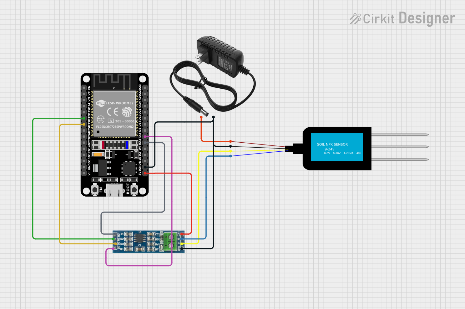
Explore Projects Built with NPK Soil Sensor
Common Applications and Use Cases
- Precision agriculture for nutrient management
- Soil health monitoring in gardens and greenhouses
- Research in agronomy and environmental science
- Educational tools for teaching soil chemistry
Technical Specifications
Key Technical Details
- Voltage: 3.3V to 5V
- Current: 35mA (typical)
- Measurement Range:
- Nitrogen: 0 to 1000 mg/kg
- Phosphorus: 0 to 200 mg/kg
- Potassium: 0 to 200 mg/kg
- Output: Digital signal via serial interface
- Accuracy: ±10%
- Operating Temperature: -10°C to +50°C
Pin Configuration and Descriptions
| Pin Number | Name | Description |
|---|---|---|
| 1 | VCC | Power supply (3.3V to 5V) |
| 2 | GND | Ground connection |
| 3 | TX | Transmit pin for serial output |
| 4 | RX | Receive pin for serial input (optional) |
Usage Instructions
How to Use the Component in a Circuit
- Power Connection: Connect the VCC pin to a 3.3V or 5V power supply and the GND pin to the ground.
- Data Connection: Connect the TX pin to the RX pin of your microcontroller (e.g., Arduino UNO) to receive data.
- Serial Communication: Set up the microcontroller to communicate with the sensor using the appropriate baud rate (usually 9600 bps).
Important Considerations and Best Practices
- Avoid placing the sensor in waterlogged soil as it may damage the sensor.
- Calibrate the sensor periodically to maintain accuracy.
- Ensure that the sensor's probes are fully inserted into the soil for reliable readings.
- Protect the electronic components from direct exposure to water and sunlight.
Example Code for Arduino UNO
#include <SoftwareSerial.h>

SoftwareSerial npkSerial(10, 11); // RX, TX

void setup() {
  // Start the serial communication with the computer
  Serial.begin(9600);
  // Start communication with the sensor at the default baud rate
  npkSerial.begin(9600);
}

void loop() {
  if (npkSerial.available()) {
    // Read the data from the sensor
    String sensorData = npkSerial.readStringUntil('\n');
    // Output the data to the Serial Monitor
    Serial.println(sensorData);
  }
  // Wait for a short period before reading again
  delay(2000);
}
Troubleshooting and FAQs
Common Issues Users Might Face
- No Data Output: Ensure that the sensor is properly powered and the TX pin is correctly connected to the microcontroller's RX pin.
- Inaccurate Readings: Calibrate the sensor as per the manufacturer's instructions and check for proper soil contact.
- Sensor Not Responding: Check for any signs of physical damage or corrosion on the sensor probes.
Solutions and Tips for Troubleshooting
- Verify all connections and ensure that the power supply is within the specified voltage range.
- Use a multimeter to check the continuity of the sensor pins and cables.
- If using long cables, consider using shielded wires to prevent signal degradation.
FAQs
Q: How often should I calibrate the NPK Soil Sensor? A: It is recommended to calibrate the sensor before the first use and periodically thereafter, depending on usage frequency and environmental conditions.
Q: Can the sensor be left in the soil permanently? A: While the sensor is designed for use in soil, prolonged exposure to harsh conditions may reduce its lifespan. It is best to use the sensor for periodic checks rather than continuous monitoring.
Q: Is the sensor waterproof? A: The sensor's probes are typically water-resistant, but the electronic components are not waterproof. Care should be taken to protect the sensor from water ingress.
Remember to consult the manufacturer's datasheet for more detailed information and contact technical support if you encounter issues not covered in this documentation.