Cirkit Designer Logo
Cirkit Designer
Your all-in-one circuit design IDE
Home / 
Component Documentation

How to Use SparkFun Serial Controlled Motor Driver: Examples, Pinouts, and Specs

Image of SparkFun Serial Controlled Motor Driver
Cirkit Designer LogoDesign with SparkFun Serial Controlled Motor Driver in Cirkit Designer

Introduction

The SparkFun Serial Controlled Motor Driver (SCMD) is a versatile and compact board designed to control motors through a serial communication interface. It is capable of driving a single bi-directional DC motor or two unidirectional DC motors. With a voltage range of 4.5V to 13.5V, it is suitable for a variety of small to medium-sized projects. Common applications include robotics, custom RC vehicles, or any project requiring motor control.

Explore Projects Built with SparkFun Serial Controlled Motor Driver

Use Cirkit Designer to design, explore, and prototype these projects online. Some projects support real-time simulation. Click "Open Project" to start designing instantly!
ESP32 Wi-Fi Controlled Dual DC Motor Driver System
Image of esp32 tbfng: A project utilizing SparkFun Serial Controlled Motor Driver in a practical application
This circuit uses an ESP32 microcontroller to control two DC motors via a SparkFun Motor Driver TB6612FNG. The motor driver is powered by a 12V battery and receives control signals from the ESP32 to manage the speed and direction of the motors.
Cirkit Designer LogoOpen Project in Cirkit Designer
Arduino UNO and L293D Motor Driver Controlled Robot with Flysky Receiver and Battery Power
Image of FLYSKY SINGLE MOTOR: A project utilizing SparkFun Serial Controlled Motor Driver in a practical application
This circuit is a remote-controlled motor driver system using an Arduino UNO, an L293D motor driver, and a Flysky receiver. The Arduino UNO receives control signals from the Flysky receiver and drives two motors through the L293D motor driver, powered by a pair of 18650 Li-ion batteries.
Cirkit Designer LogoOpen Project in Cirkit Designer
Arduino UNO and Motor Driver Controlled Dual Motor System with LED Indicator
Image of broken: A project utilizing SparkFun Serial Controlled Motor Driver in a practical application
This circuit uses an Arduino UNO to control a motor driver (SparkFun TB6612FNG) and a four-pin LED. The Arduino provides power and control signals to the motor driver, which in turn drives two motors, while the LED is connected through resistors to various digital pins on the Arduino for color control.
Cirkit Designer LogoOpen Project in Cirkit Designer
Arduino-Controlled Dual Motor Driver with IR Sensing
Image of Line follower 14 IR Sensor channel: A project utilizing SparkFun Serial Controlled Motor Driver in a practical application
This circuit controls two DC motors using a TB6612FNG motor driver, which is interfaced with an Arduino Mega 2560 microcontroller. The Arduino provides PWM signals to control the speed and direction of the motors. Multiple IR sensors are connected to the Arduino's analog inputs, likely for sensing the environment or for line-following capabilities in a robot.
Cirkit Designer LogoOpen Project in Cirkit Designer

Explore Projects Built with SparkFun Serial Controlled Motor Driver

Use Cirkit Designer to design, explore, and prototype these projects online. Some projects support real-time simulation. Click "Open Project" to start designing instantly!
Image of esp32 tbfng: A project utilizing SparkFun Serial Controlled Motor Driver in a practical application
ESP32 Wi-Fi Controlled Dual DC Motor Driver System
This circuit uses an ESP32 microcontroller to control two DC motors via a SparkFun Motor Driver TB6612FNG. The motor driver is powered by a 12V battery and receives control signals from the ESP32 to manage the speed and direction of the motors.
Cirkit Designer LogoOpen Project in Cirkit Designer
Image of FLYSKY SINGLE MOTOR: A project utilizing SparkFun Serial Controlled Motor Driver in a practical application
Arduino UNO and L293D Motor Driver Controlled Robot with Flysky Receiver and Battery Power
This circuit is a remote-controlled motor driver system using an Arduino UNO, an L293D motor driver, and a Flysky receiver. The Arduino UNO receives control signals from the Flysky receiver and drives two motors through the L293D motor driver, powered by a pair of 18650 Li-ion batteries.
Cirkit Designer LogoOpen Project in Cirkit Designer
Image of broken: A project utilizing SparkFun Serial Controlled Motor Driver in a practical application
Arduino UNO and Motor Driver Controlled Dual Motor System with LED Indicator
This circuit uses an Arduino UNO to control a motor driver (SparkFun TB6612FNG) and a four-pin LED. The Arduino provides power and control signals to the motor driver, which in turn drives two motors, while the LED is connected through resistors to various digital pins on the Arduino for color control.
Cirkit Designer LogoOpen Project in Cirkit Designer
Image of Line follower 14 IR Sensor channel: A project utilizing SparkFun Serial Controlled Motor Driver in a practical application
Arduino-Controlled Dual Motor Driver with IR Sensing
This circuit controls two DC motors using a TB6612FNG motor driver, which is interfaced with an Arduino Mega 2560 microcontroller. The Arduino provides PWM signals to control the speed and direction of the motors. Multiple IR sensors are connected to the Arduino's analog inputs, likely for sensing the environment or for line-following capabilities in a robot.
Cirkit Designer LogoOpen Project in Cirkit Designer

Technical Specifications

Key Technical Details

  • Voltage Range: 4.5V to 13.5V
  • Continuous Current: Up to 3A
  • Peak Current: Up to 5A (for a few milliseconds)
  • Communication Interface: TTL Serial (5V logic level)
  • Baud Rate: 9600 to 115200 bps (default 9600)
  • Dimensions: 1.33 x 0.90 inches

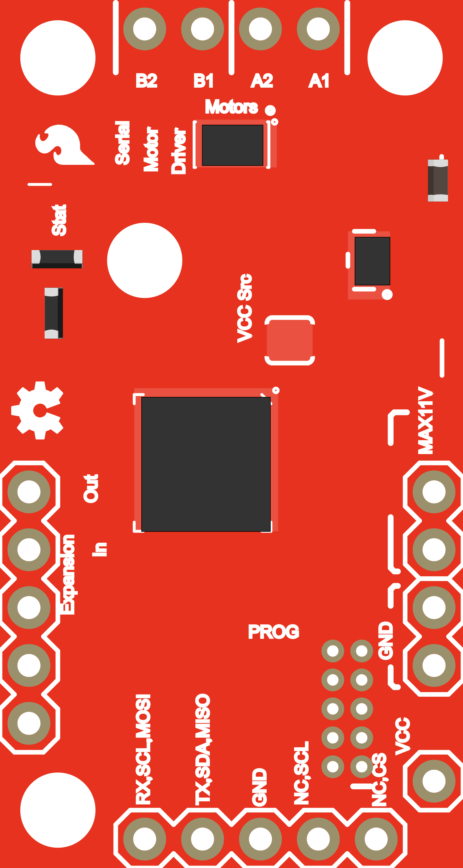
Pin Configuration and Descriptions

Pin Number Name Description
1 GND Ground connection
2 VIN Voltage input for motor power (4.5V to 13.5V)
3 TX Transmit pin for serial communication
4 RX Receive pin for serial communication
5 A1 Motor A output 1
6 A2 Motor A output 2
7 B1 Motor B output 1 (if using two unidirectional motors)
8 B2 Motor B output 2 (if using two unidirectional motors)

Usage Instructions

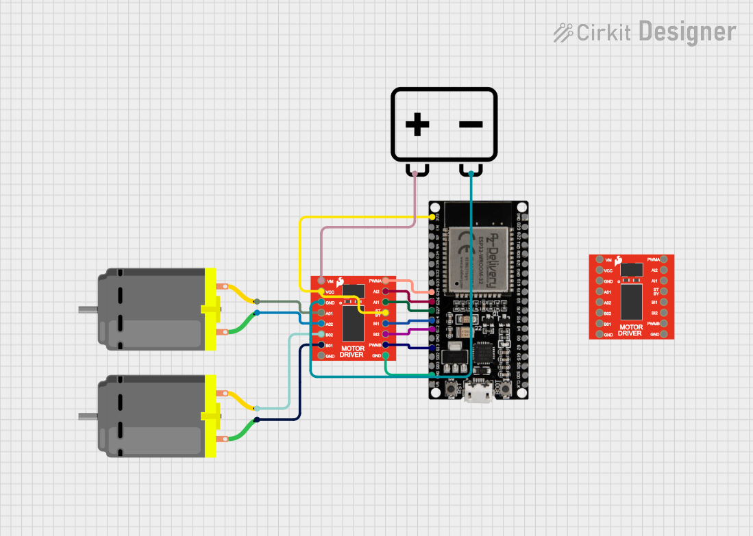
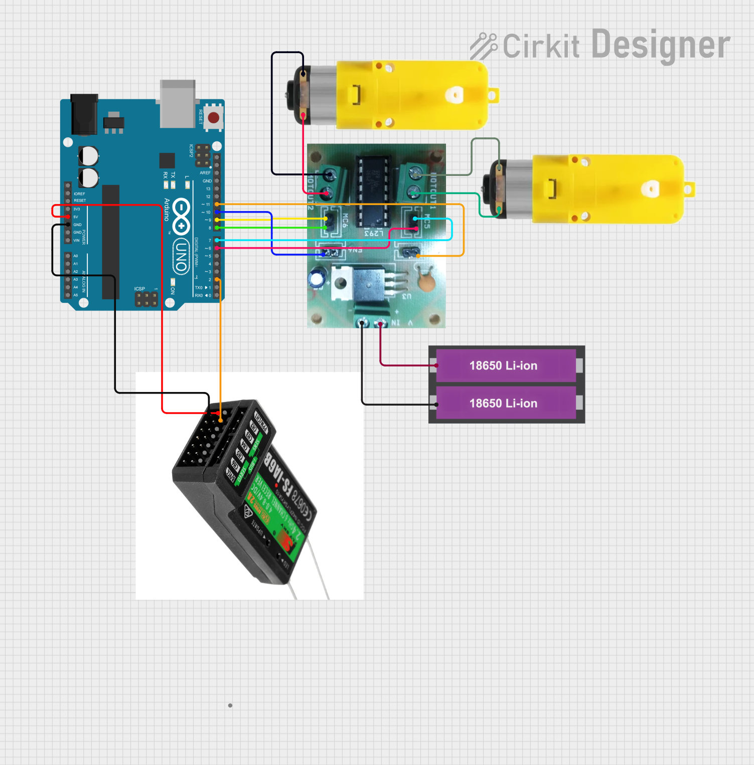
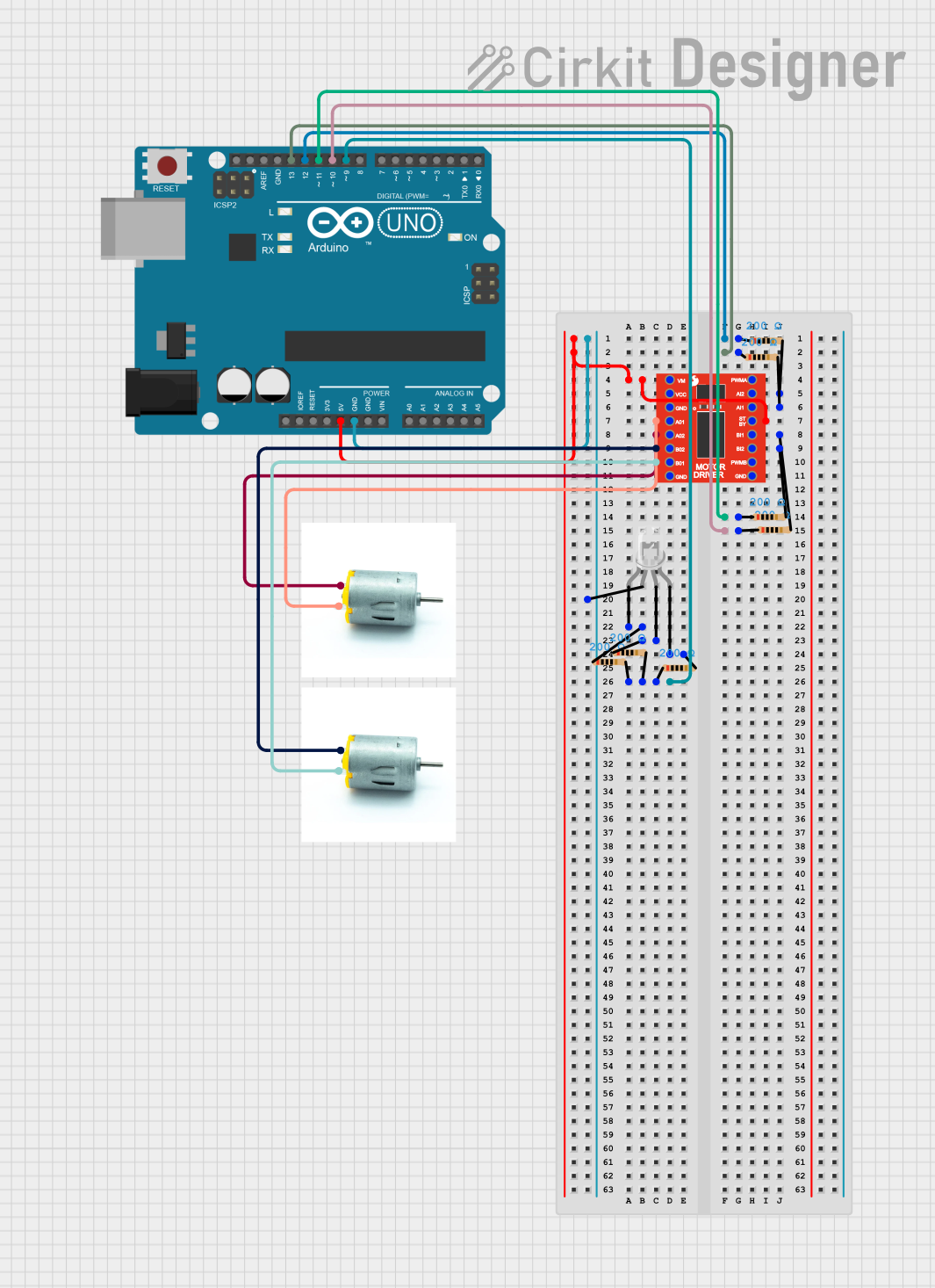
Connecting the Motor Driver

  1. Connect the motor(s) to the SCMD board's output pins (A1, A2, B1, B2).
  2. Supply the motor voltage to the VIN pin, ensuring it is within the specified range.
  3. Connect the ground pin (GND) to the system's ground.
  4. Connect the TX and RX pins to the corresponding RX and TX pins of the controller (e.g., Arduino UNO).

Serial Communication

The SCMD accepts serial commands for controlling motor speed and direction. The default baud rate is 9600 bps, but it can be adjusted to suit your needs.

Arduino Code Example

Here is a simple example of how to control the SCMD with an Arduino UNO:

#include <SoftwareSerial.h>

SoftwareSerial scmdSerial(10, 11); // RX, TX

void setup() {
  scmdSerial.begin(9600); // Start serial communication at 9600 bps
}

void loop() {
  // Command to set motor A to full speed forward
  scmdSerial.write(0x88); // Start byte
  scmdSerial.write(0x01); // Motor A
  scmdSerial.write(0xFF); // Speed (0xFF for full speed)
  
  delay(2000); // Run for 2 seconds
  
  // Command to stop motor A
  scmdSerial.write(0x88); // Start byte
  scmdSerial.write(0x01); // Motor A
  scmdSerial.write(0x00); // Speed (0x00 to stop)
  
  delay(2000); // Stop for 2 seconds
}

Important Considerations and Best Practices

  • Always ensure the power supply voltage and current do not exceed the SCMD's ratings.
  • Use a separate power supply for the motors to prevent noise and voltage drops on the logic side.
  • Include a flyback diode across the motor terminals if driving inductive loads to protect the driver from voltage spikes.

Troubleshooting and FAQs

Common Issues

  • Motor not responding: Check connections, ensure power supply is within the specified range, and verify that serial commands are being sent correctly.
  • Unexpected behavior: Reset the SCMD and check for any programming errors in the serial commands.

Solutions and Tips for Troubleshooting

  • Double-check wiring, especially the TX and RX connections.
  • Use a multimeter to verify the voltage at VIN and the motor outputs.
  • Ensure that the serial baud rate of the SCMD matches that of the controller.

FAQs

Q: Can I control stepper motors with the SCMD? A: No, the SCMD is designed for DC motors. Stepper motors require a different type of driver.

Q: What is the maximum number of motors I can control with one SCMD? A: You can control one bi-directional DC motor or two unidirectional DC motors.

Q: How do I change the baud rate? A: You can change the baud rate by sending a specific serial command to the SCMD. Refer to the SCMD datasheet for the command structure.

This documentation provides an overview of the SparkFun Serial Controlled Motor Driver, its technical specifications, usage instructions, and troubleshooting tips. For more detailed information, refer to the official datasheet and user manual provided by SparkFun.