
How to Use XPORT-DIRECT: Examples, Pinouts, and Specs
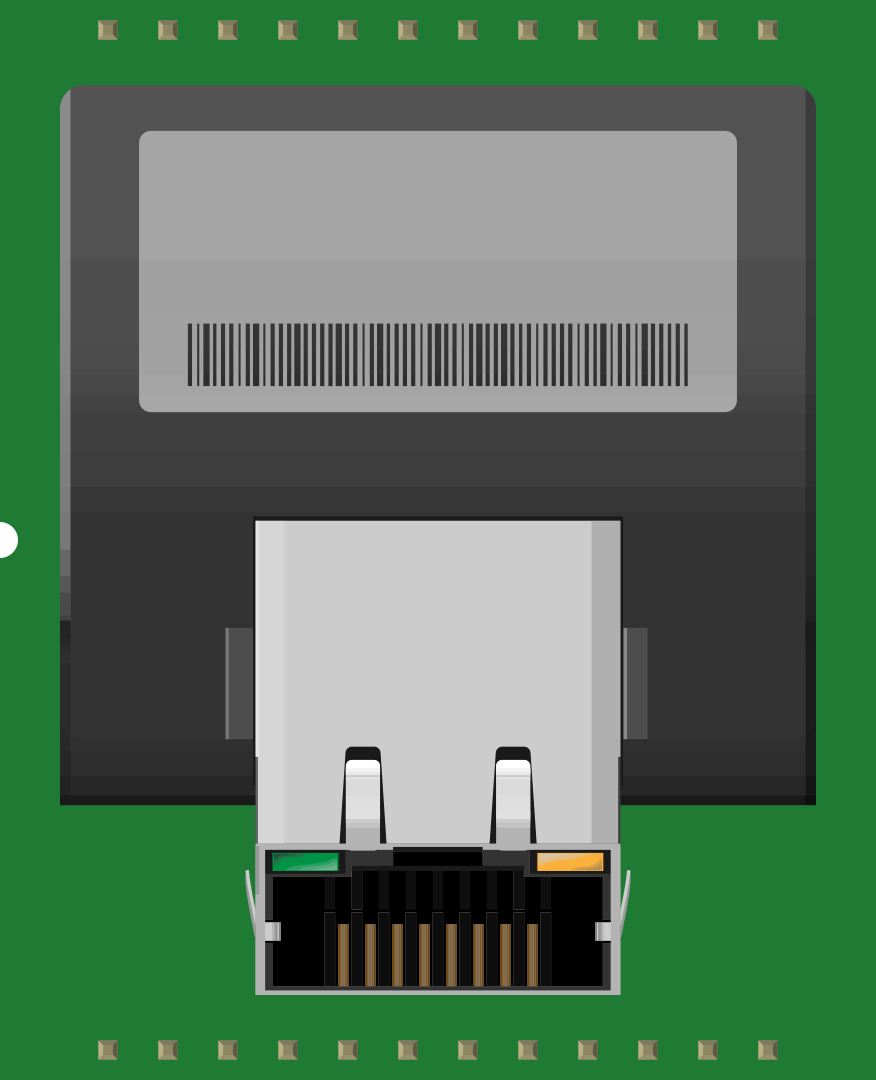
 Design with XPORT-DIRECT in Cirkit Designer
Introduction
The XPORT-DIRECT by Lantronix is a compact and versatile communication module designed to provide seamless Ethernet connectivity for electronic devices. It simplifies the process of integrating network capabilities into embedded systems, making it an ideal solution for applications requiring remote monitoring, data transmission, or control over Ethernet.
Explore Projects Built with XPORT-DIRECT
 Open Project in Cirkit Designer
 Open Project in Cirkit Designer
 Open Project in Cirkit Designer
 Open Project in Cirkit Designer
Explore Projects Built with XPORT-DIRECT
Open Project in Cirkit DesignerOpen Project in Cirkit DesignerOpen Project in Cirkit DesignerOpen Project in Cirkit DesignerCommon Applications and Use Cases
- Industrial automation and control systems
- Remote device monitoring and management
- IoT (Internet of Things) applications
- Home automation systems
- Data logging and telemetry
- Embedded systems requiring Ethernet connectivity
Technical Specifications
Key Technical Details
| Parameter | Value |
|---|---|
| Manufacturer | Lantronix |
| Part ID | XPort Direct |
| Network Interface | 10/100 Mbps Ethernet |
| Input Voltage Range | 3.3V DC |
| Power Consumption | 200 mA (typical) |
| Operating Temperature | -40°C to +85°C |
| Dimensions | 33.9 mm x 16.25 mm x 13.5 mm |
| Protocol Support | TCP/IP, UDP, HTTP, FTP, Telnet, DHCP, etc. |
| Serial Interface | UART (up to 921.6 kbps) |
Pin Configuration and Descriptions
The XPORT-DIRECT module has a 10-pin interface for easy integration into your circuit. Below is the pinout and description:
| Pin Number | Pin Name | Description |
|---|---|---|
| 1 | GND | Ground |
| 2 | VCC | Power supply input (3.3V DC) |
| 3 | TXD | Transmit data (UART output) |
| 4 | RXD | Receive data (UART input) |
| 5 | RTS | Request to send (UART control signal) |
| 6 | CTS | Clear to send (UART control signal) |
| 7 | RESET | Active-low reset input |
| 8 | LINK LED | Ethernet link status indicator |
| 9 | ACT LED | Ethernet activity status indicator |
| 10 | NC | Not connected |
Usage Instructions
How to Use the XPORT-DIRECT in a Circuit
- Power Supply: Connect the VCC pin to a regulated 3.3V DC power source and the GND pin to the ground of your circuit.
- UART Communication: Connect the TXD and RXD pins to the UART interface of your microcontroller or host device. Optionally, connect RTS and CTS for hardware flow control.
- Ethernet Connection: Attach the Ethernet port of the XPORT-DIRECT to your network using a standard RJ45 cable.
- Reset: Use the RESET pin to initialize the module if needed. Pull this pin low momentarily to reset the device.
- LED Indicators: Monitor the LINK LED and ACT LED for Ethernet connection and activity status.
Important Considerations and Best Practices
- Ensure the power supply is stable and within the specified voltage range (3.3V DC).
- Use proper decoupling capacitors near the VCC pin to minimize noise.
- If using hardware flow control, ensure your microcontroller supports RTS/CTS signals.
- Configure the module's network settings (e.g., IP address, subnet mask) using the provided configuration tools or commands.
- Avoid exposing the module to extreme temperatures or humidity beyond its operating range.
Example: Connecting XPORT-DIRECT to an Arduino UNO
Below is an example of how to connect the XPORT-DIRECT to an Arduino UNO and send data over Ethernet.
Wiring Diagram
| XPORT-DIRECT Pin | Arduino UNO Pin |
|---|---|
| VCC | 3.3V |
| GND | GND |
| TXD | RX (Pin 0) |
| RXD | TX (Pin 1) |
| RESET | Digital Pin 7 |
Arduino Code Example
// Include necessary libraries
#include <SoftwareSerial.h>

// Define pins for XPORT-DIRECT
#define RESET_PIN 7

// Create a SoftwareSerial object for communication
SoftwareSerial xportSerial(0, 1); // RX, TX

void setup() {
  // Initialize serial communication
  Serial.begin(9600); // For debugging
  xportSerial.begin(9600); // For XPORT-DIRECT communication

  // Configure the RESET pin
  pinMode(RESET_PIN, OUTPUT);
  digitalWrite(RESET_PIN, HIGH); // Keep the module active

  // Send a test message
  Serial.println("Sending data to XPORT-DIRECT...");
  xportSerial.println("Hello, Ethernet!");
}

void loop() {
  // Check for incoming data from XPORT-DIRECT
  if (xportSerial.available()) {
    String data = xportSerial.readString();
    Serial.print("Received from XPORT-DIRECT: ");
    Serial.println(data);
  }

  // Check for user input from Serial Monitor
  if (Serial.available()) {
    String userInput = Serial.readString();
    xportSerial.println(userInput); // Send to XPORT-DIRECT
  }
}
Notes:
- Ensure the Arduino UNO is powered via USB or an external power source.
- Use a level shifter if the Arduino operates at 5V logic levels to avoid damaging the XPORT-DIRECT.
Troubleshooting and FAQs
Common Issues and Solutions
No Ethernet Connectivity
- Verify the Ethernet cable is securely connected.
- Check the LINK LED and ACT LED for activity.
- Ensure the module's network settings (IP address, subnet mask) are correctly configured.
No UART Communication
- Confirm the TXD and RXD pins are correctly connected to the host device.
- Check the baud rate settings on both the XPORT-DIRECT and the host device.
Module Not Powering On
- Ensure the VCC pin is receiving a stable 3.3V DC supply.
- Check for loose connections or damaged wires.
Reset Pin Not Working
- Ensure the RESET pin is pulled low for at least 100 ms to trigger a reset.
FAQs
Q: Can the XPORT-DIRECT operate at 5V?
A: No, the XPORT-DIRECT requires a 3.3V DC power supply. Using 5V may damage the module.
Q: How do I configure the network settings?
A: Use the Lantronix DeviceInstaller software or send configuration commands via the UART interface.
Q: Is the XPORT-DIRECT compatible with other microcontrollers?
A: Yes, it can be used with any microcontroller that supports UART communication.
Q: Can I use the XPORT-DIRECT for wireless communication?
A: No, the XPORT-DIRECT is designed for wired Ethernet connectivity only.