Cirkit Designer
Your all-in-one circuit design IDE
Home /
Component Documentation
How to Use 1 Channel 5V Relay Module: Examples, Pinouts, and Specs
Introduction
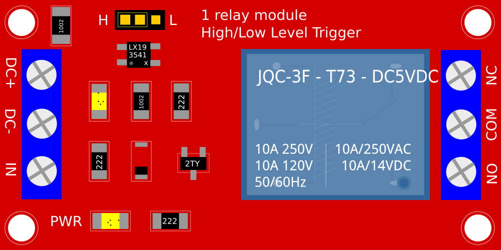
The 1 Channel 5V Relay Module is an electronic switch that allows you to control high power devices with a low voltage signal, typically from a microcontroller like an Arduino. This relay module is widely used in robotics, home automation, and various DIY projects where it is necessary to control AC or DC loads.
Explore Projects Built with 1 Channel 5V Relay Module
DC-DC Converter and Relay Module Power Distribution System

This circuit consists of a DC-DC converter powering a 6-channel power module, which in turn supplies 5V to a 2-relay module. The power module distributes the converted voltage to the relay module, enabling it to control external devices.
Battery-Powered IR Sensor Controlled Relay Module

This circuit uses an IR sensor to control a 1 Channel 5V Relay Module, which is powered by a 9V battery. The IR sensor detects an object and sends a signal to the relay module to switch its state, enabling or disabling the connected load.
Battery-Powered 4-Channel Relay Control with LED Indicators

This circuit consists of a 5V battery powering a 4-channel relay module, which controls four LEDs (red, yellow, green, and blue) through individual resistors. Each relay channel is activated by a corresponding SPST toggle switch, allowing manual control of the LEDs.
Arduino Relay-Controlled LED Circuit
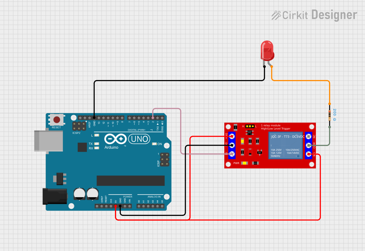
This circuit utilizes an Arduino UNO to control a 1 Channel 5V Relay Module, which in turn can switch a load on and off. The relay is activated by a digital signal from the Arduino on pin D2, and an LED is connected to indicate the relay's status, with a resistor limiting the current to the LED.
Explore Projects Built with 1 Channel 5V Relay Module
DC-DC Converter and Relay Module Power Distribution System
This circuit consists of a DC-DC converter powering a 6-channel power module, which in turn supplies 5V to a 2-relay module. The power module distributes the converted voltage to the relay module, enabling it to control external devices.
Battery-Powered IR Sensor Controlled Relay Module
This circuit uses an IR sensor to control a 1 Channel 5V Relay Module, which is powered by a 9V battery. The IR sensor detects an object and sends a signal to the relay module to switch its state, enabling or disabling the connected load.
Battery-Powered 4-Channel Relay Control with LED Indicators
This circuit consists of a 5V battery powering a 4-channel relay module, which controls four LEDs (red, yellow, green, and blue) through individual resistors. Each relay channel is activated by a corresponding SPST toggle switch, allowing manual control of the LEDs.
Arduino Relay-Controlled LED Circuit
This circuit utilizes an Arduino UNO to control a 1 Channel 5V Relay Module, which in turn can switch a load on and off. The relay is activated by a digital signal from the Arduino on pin D2, and an LED is connected to indicate the relay's status, with a resistor limiting the current to the LED.
Common Applications and Use Cases
- Home automation (e.g., turning lights on/off)
- Controlling motors in robotics
- Switching power to devices like fans, pumps, and other machinery
Technical Specifications
Key Technical Details
- Operating Voltage (VCC): 5V DC
- Trigger Voltage (IN): 0-1.5V (LOW to trigger), 2.5-5V (HIGH to trigger)
- Current Consumption: 15-20mA
- Maximum AC Load: 250VAC @ 10A
- Maximum DC Load: 30VDC @ 10A
- Switching Time: Typically 5-10ms
Pin Configuration and Descriptions
| Pin | Description |
|---|---|
| VCC | Connect to 5V power supply |
| GND | Connect to ground |
| IN | Control signal input from microcontroller |
| NO | Normally open contact |
| COM | Common contact |
| NC | Normally closed contact |
Usage Instructions
How to Use the Component in a Circuit
- Connect the VCC pin to a 5V power supply.
- Connect the GND pin to the ground of the power supply.
- Connect the IN pin to a digital output pin of a microcontroller.
- Connect the device you want to control to the NO or NC and COM pins.
Important Considerations and Best Practices
- Ensure the power supply does not exceed 5V as it may damage the relay.
- Do not exceed the maximum load ratings to prevent damage and ensure safety.
- Use a flyback diode when controlling inductive loads to prevent back EMF damage.
- Isolate the high voltage circuit from the low voltage control circuit.
Example Code for Arduino UNO
// Define the relay control pin
const int relayPin = 2;

void setup() {
  // Set the relay pin as an output
  pinMode(relayPin, OUTPUT);
  // Start with the relay off
  digitalWrite(relayPin, LOW);
}

void loop() {
  // Turn on the relay
  digitalWrite(relayPin, HIGH);
  delay(5000); // Keep the relay on for 5 seconds
  // Turn off the relay
  digitalWrite(relayPin, LOW);
  delay(5000); // Keep the relay off for 5 seconds
}
Troubleshooting and FAQs
Common Issues Users Might Face
- Relay does not switch: Check the control signal and power connections.
- Intermittent operation: Ensure solid connections and that the power supply is stable.
- Clicking sound but no action: Verify the load does not exceed the relay's rating.
Solutions and Tips for Troubleshooting
- Double-check wiring, especially the control signal and power supply.
- Use a multimeter to verify the presence of the control voltage at the IN pin.
- Ensure the microcontroller's ground is connected to the relay module's ground.
FAQs
Q: Can I control this relay with a 3.3V signal? A: The relay might not reliably trigger with 3.3V. It is designed for 5V signals.
Q: Is it safe to control AC devices with this relay? A: Yes, but ensure you have proper knowledge of working with high voltage and take necessary safety precautions.
Q: Can I use PWM to control the relay? A: No, the relay requires a steady HIGH or LOW signal to change states. PWM may cause erratic behavior.