How to Use Power Distribution Board (PDB) 60A: Examples, Pinouts, and Specs
Introduction
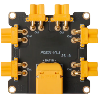
The Holybro Power Distribution Board (PDB) 60A is a robust and efficient circuit board designed to distribute electrical power to multiple components in a system. With a maximum current handling capacity of 60 amps, this PDB is ideal for high-power applications such as drones, RC vehicles, robotics, and other electronic systems requiring reliable power management.
The PDB features multiple output terminals, enabling seamless connection to various devices while ensuring efficient power distribution and minimizing the risk of overload. Its compact design and high current capacity make it a popular choice for hobbyists and professionals alike.
Explore Projects Built with Power Distribution Board (PDB) 60A


Explore Projects Built with Power Distribution Board (PDB) 60A
Common Applications
- Multirotor drones (e.g., quadcopters, hexacopters)
- RC vehicles (cars, boats, planes)
- Robotics and automation systems
- High-power LED lighting systems
- Custom electronic projects requiring centralized power distribution
Technical Specifications
Key Technical Details
| Parameter | Specification |
|---|---|
| Manufacturer | Holybro |
| Maximum Current Capacity | 60A |
| Input Voltage Range | 2S–6S LiPo (7.4V–25.2V) |
| Output Voltage | Same as input voltage (unregulated) |
| Dimensions | 36mm x 50mm |
| Weight | 10g |
| PCB Material | High-quality FR4 |
| Connector Type | Solder pads for input/output |
| Additional Features | Integrated filtering capacitors |
Pin Configuration and Descriptions
The Holybro PDB 60A features solder pads for both input and output connections. Below is a description of the key pads:
| Pad Name | Description |
|---|---|
| VIN+ | Positive input terminal for connecting the battery (2S–6S LiPo). |
| VIN- | Negative input terminal for connecting the battery ground. |
| VOUT+ | Positive output terminals for distributing power to connected devices. |
| VOUT- | Negative output terminals for distributing ground to connected devices. |
| Capacitor Pads | Pads for integrated capacitors to reduce voltage ripple and noise. |
Usage Instructions
How to Use the PDB in a Circuit
- Prepare the PDB: Ensure the PDB is clean and free of debris. Inspect the solder pads for any damage.
- Connect the Battery:
- Solder the positive lead of the battery to the VIN+ pad.
- Solder the negative lead of the battery to the VIN- pad.
- Connect Devices:
- Solder the positive power leads of your devices (e.g., ESCs, motors, LEDs) to the VOUT+ pads.
- Solder the ground leads of your devices to the VOUT- pads.
- Secure the Connections: Use heat shrink tubing or electrical tape to insulate exposed wires and solder joints.
- Mount the PDB: Attach the PDB securely to your project using screws, standoffs, or double-sided tape. Ensure it is isolated from conductive surfaces to prevent short circuits.
Important Considerations and Best Practices
- Current Handling: Do not exceed the 60A maximum current rating to avoid overheating or damage.
- Voltage Compatibility: Ensure the input voltage is within the 2S–6S LiPo range (7.4V–25.2V).
- Soldering Tips: Use a high-quality soldering iron and appropriate solder to ensure strong, reliable connections.
- Cooling: In high-current applications, ensure adequate airflow around the PDB to prevent overheating.
- Polarity: Double-check all connections for correct polarity before powering on the system.
Example: Connecting the PDB to an Arduino UNO
While the PDB itself does not directly interface with an Arduino, it can be used to power peripherals connected to the Arduino. Below is an example of powering an Arduino UNO and a motor driver using the PDB:
/* Example: Controlling a motor with Arduino UNO and PDB
   - The PDB distributes power to the motor driver and Arduino.
   - Ensure the PDB is connected to a 2S–6S LiPo battery.
*/

// Define motor control pins
const int motorPin1 = 9; // Motor control pin 1
const int motorPin2 = 10; // Motor control pin 2

void setup() {
  // Set motor pins as outputs
  pinMode(motorPin1, OUTPUT);
  pinMode(motorPin2, OUTPUT);
}

void loop() {
  // Rotate motor in one direction
  digitalWrite(motorPin1, HIGH);
  digitalWrite(motorPin2, LOW);
  delay(2000); // Run for 2 seconds

  // Stop motor
  digitalWrite(motorPin1, LOW);
  digitalWrite(motorPin2, LOW);
  delay(1000); // Pause for 1 second

  // Rotate motor in the opposite direction
  digitalWrite(motorPin1, LOW);
  digitalWrite(motorPin2, HIGH);
  delay(2000); // Run for 2 seconds

  // Stop motor
  digitalWrite(motorPin1, LOW);
  digitalWrite(motorPin2, LOW);
  delay(1000); // Pause for 1 second
}
Troubleshooting and FAQs
Common Issues and Solutions
| Issue | Possible Cause | Solution |
|---|---|---|
| PDB overheating | Exceeding the 60A current limit | Reduce the load or use a higher-capacity PDB. |
| Devices not receiving power | Poor solder connections | Re-solder the connections and ensure proper contact. |
| Voltage ripple affecting devices | Insufficient filtering | Add external capacitors to reduce noise. |
| Short circuit | Incorrect wiring or exposed connections | Double-check wiring and insulate exposed areas. |
FAQs
Can I use the PDB with a 12V power supply instead of a LiPo battery?
- Yes, as long as the voltage is within the 7.4V–25.2V range, the PDB can be used with other power sources.
How many devices can I connect to the PDB?
- The number of devices depends on their total current draw. Ensure the combined current does not exceed 60A.
Do I need additional cooling for the PDB?
- In high-current applications, it is recommended to provide adequate airflow or cooling to prevent overheating.
Can I use this PDB for a 7S or higher LiPo battery?
- No, the PDB is designed for 2S–6S LiPo batteries only. Using a higher voltage may damage the board.
This documentation provides a comprehensive guide to using the Holybro Power Distribution Board (PDB) 60A effectively. For further assistance, refer to the manufacturer's support resources.