
How to Use Hirose DF13A-8P-1.25H Right-Angle Header: Examples, Pinouts, and Specs

 Design with Hirose DF13A-8P-1.25H Right-Angle Header in Cirkit Designer
Introduction
The Hirose DF13A-8P-1.25H is a compact, 8-position right-angle header connector designed for reliable and durable connections in electronic devices. With a 1.25mm pitch, this connector is ideal for applications where space-saving is critical. Its robust design ensures secure mating with corresponding receptacles, making it suitable for a wide range of electronic and industrial applications.
Explore Projects Built with Hirose DF13A-8P-1.25H Right-Angle Header
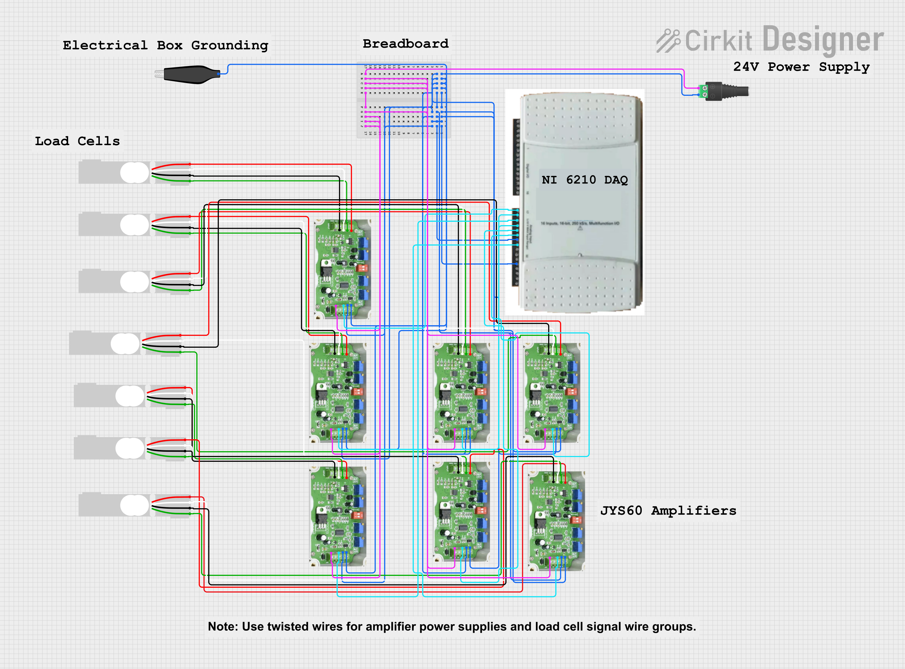 Open Project in Cirkit Designer
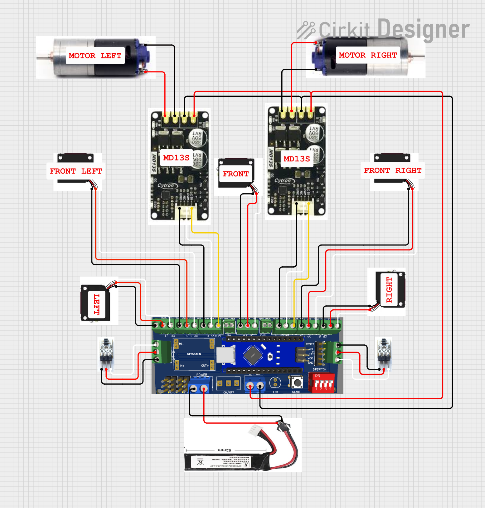 Open Project in Cirkit Designer
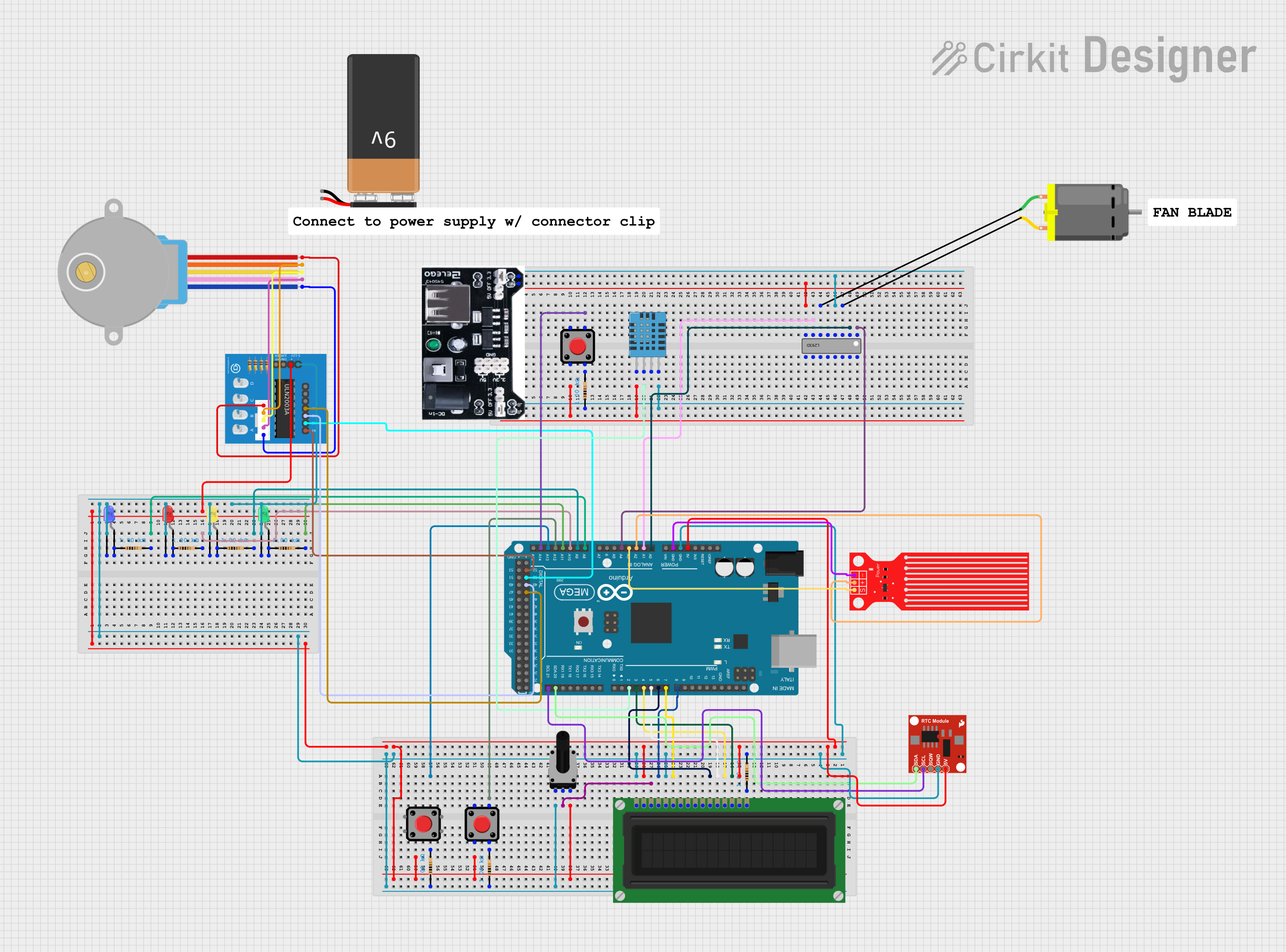 Open Project in Cirkit Designer
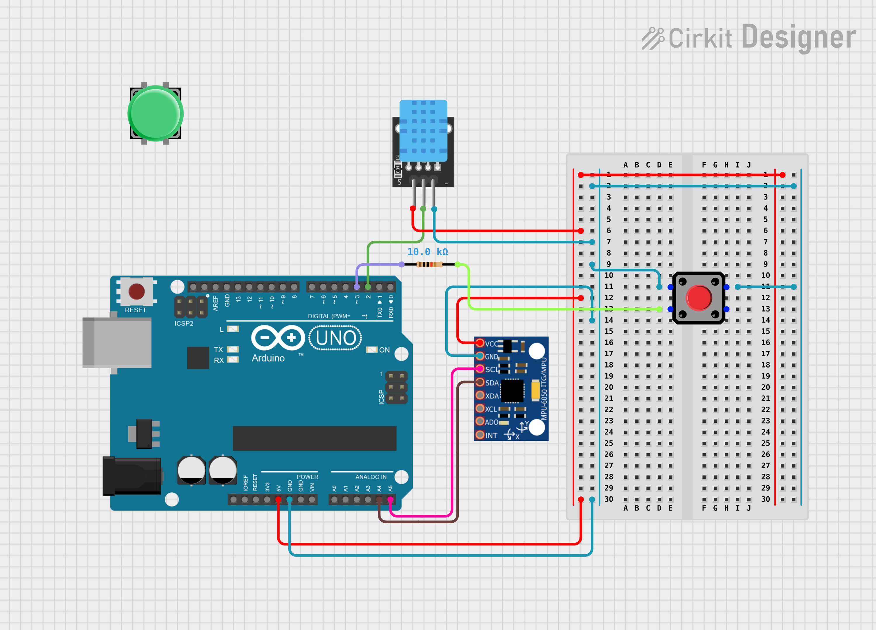 Open Project in Cirkit Designer
Explore Projects Built with Hirose DF13A-8P-1.25H Right-Angle Header
Open Project in Cirkit DesignerOpen Project in Cirkit DesignerOpen Project in Cirkit DesignerOpen Project in Cirkit DesignerCommon Applications
- Consumer electronics (e.g., cameras, handheld devices)
- Industrial equipment
- Robotics and automation systems
- Embedded systems and PCBs with limited space
- Signal and low-power connections in compact circuits
Technical Specifications
Key Technical Details
| Parameter | Value |
|---|---|
| Manufacturer | Hirose Electric |
| Part Number | DF13A-8P-1.25H |
| Connector Type | Right-angle header |
| Number of Positions | 8 |
| Pitch | 1.25mm |
| Mounting Type | Surface Mount Technology (SMT) |
| Contact Material | Phosphor bronze |
| Contact Plating | Tin |
| Insulation Material | Polyamide (UL94V-0 rated) |
| Current Rating | 1A per contact |
| Voltage Rating | 100V AC/DC |
| Operating Temperature | -35°C to +85°C |
| Mating Cycles | 30 cycles |
Pin Configuration and Descriptions
The DF13A-8P-1.25H has 8 pins arranged in a single row. Below is the pin configuration:
| Pin Number | Description | Notes |
|---|---|---|
| 1 | Signal/Power Line 1 | User-defined signal or power |
| 2 | Signal/Power Line 2 | User-defined signal or power |
| 3 | Signal/Power Line 3 | User-defined signal or power |
| 4 | Signal/Power Line 4 | User-defined signal or power |
| 5 | Signal/Power Line 5 | User-defined signal or power |
| 6 | Signal/Power Line 6 | User-defined signal or power |
| 7 | Signal/Power Line 7 | User-defined signal or power |
| 8 | Signal/Power Line 8 | User-defined signal or power |
Usage Instructions
How to Use the Component in a Circuit
- PCB Design: Ensure the PCB layout matches the 1.25mm pitch of the DF13A-8P-1.25H. Use the recommended footprint provided in the component datasheet for accurate placement.
- Soldering:
- Use a reflow soldering process for surface mounting.
- Ensure the solder paste is applied evenly to avoid cold solder joints.
- Mating: Pair the header with a compatible DF13 series receptacle (e.g., DF13-8S-1.25C) for a secure connection.
- Wiring: Connect the corresponding wires or traces to the appropriate pins based on your circuit design.
Important Considerations and Best Practices
- Current and Voltage Ratings: Do not exceed the specified 1A per contact and 100V AC/DC ratings to avoid damage.
- Mating Cycles: The connector is rated for 30 mating cycles. Avoid excessive mating/unmating to maintain reliability.
- Temperature Range: Operate the connector within the specified temperature range (-35°C to +85°C) to prevent material degradation.
- Alignment: Ensure proper alignment when mating the header with the receptacle to avoid bent pins or poor connections.
Example: Connecting to an Arduino UNO
The DF13A-8P-1.25H can be used to connect peripheral devices to an Arduino UNO. Below is an example of wiring and code to read a signal from a sensor connected via the DF13 header.
Circuit Setup
- Connect the sensor's output to Pin 1 of the DF13 header.
- Connect the DF13 header's Pin 2 to the Arduino's GND.
- Connect the DF13 header's Pin 3 to the Arduino's 5V pin (if the sensor requires power).
Arduino Code
// Example code to read a sensor value connected via DF13A-8P-1.25H header
const int sensorPin = A0; // Pin A0 is connected to DF13 header Pin 1

void setup() {
  Serial.begin(9600); // Initialize serial communication at 9600 baud
  pinMode(sensorPin, INPUT); // Set the sensor pin as input
}

void loop() {
  int sensorValue = analogRead(sensorPin); // Read the sensor value
  Serial.print("Sensor Value: ");
  Serial.println(sensorValue); // Print the sensor value to the Serial Monitor
  delay(500); // Wait for 500ms before the next reading
}
Troubleshooting and FAQs
Common Issues and Solutions
Poor Connection or Intermittent Signal
- Cause: Misalignment during mating or bent pins.
- Solution: Ensure proper alignment and inspect pins for damage. Replace the connector if necessary.
Cold Solder Joints
- Cause: Insufficient heat during soldering.
- Solution: Reflow solder the connector using the recommended temperature profile.
Exceeding Current/Voltage Ratings
- Cause: Overloading the connector.
- Solution: Verify that the current and voltage do not exceed 1A and 100V AC/DC, respectively.
Connector Damage After Multiple Mating Cycles
- Cause: Exceeding the rated 30 mating cycles.
- Solution: Replace the connector if it shows signs of wear or damage.
FAQs
Q: Can the DF13A-8P-1.25H handle high-frequency signals?
A: Yes, the connector can handle high-frequency signals, but ensure proper PCB design to minimize signal loss or interference.
Q: Is the DF13A-8P-1.25H compatible with other DF13 series connectors?
A: Yes, it is compatible with other DF13 series receptacles, such as DF13-8S-1.25C.
Q: Can I use this connector in outdoor applications?
A: The DF13A-8P-1.25H is not specifically designed for outdoor use. If used outdoors, ensure it is protected from moisture and extreme environmental conditions.
Q: What is the recommended soldering temperature?
A: Follow the reflow soldering temperature profile provided in the Hirose DF13 series datasheet for optimal results.