How to Use SparkFun Nano Power Timer - TPL5110: Examples, Pinouts, and Specs
Introduction
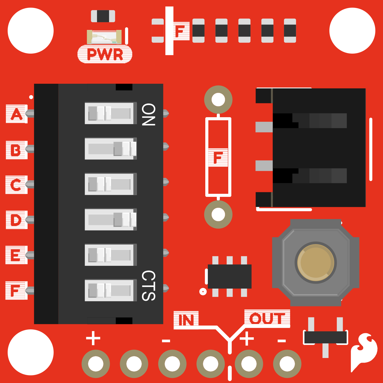
The SparkFun Nano Power Timer - TPL5110 is a specialized electronic component designed to efficiently manage power consumption in battery-powered applications. This breakout board utilizes the TPL5110 chip to enable timed power cycles, allowing users to schedule when their project turns on and off. This functionality is particularly useful in applications where power conservation is critical, such as remote sensing, data logging, and portable electronics.
Explore Projects Built with SparkFun Nano Power Timer - TPL5110
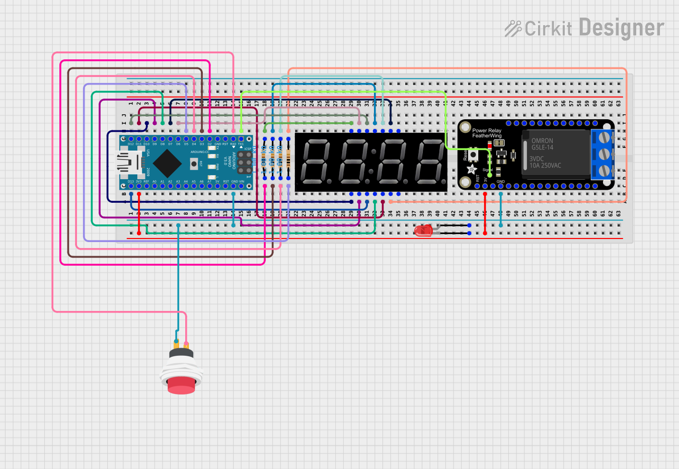
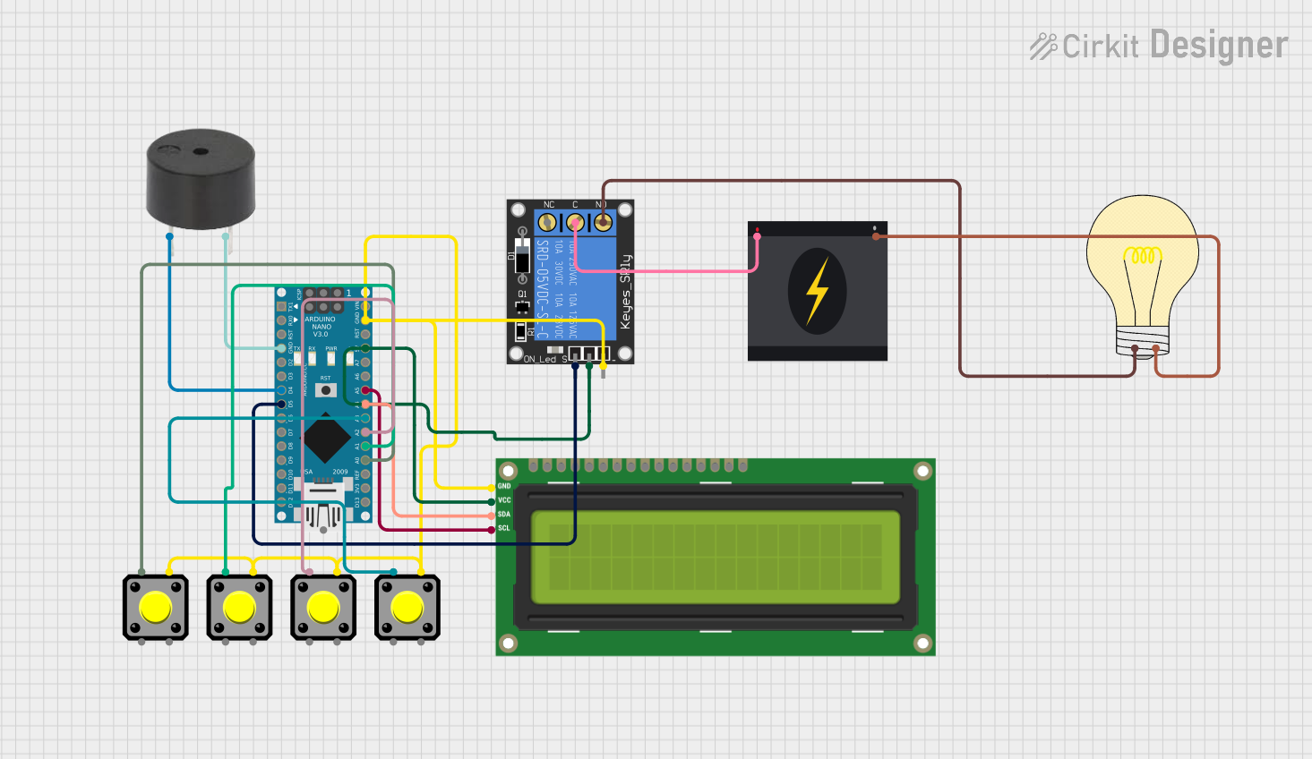
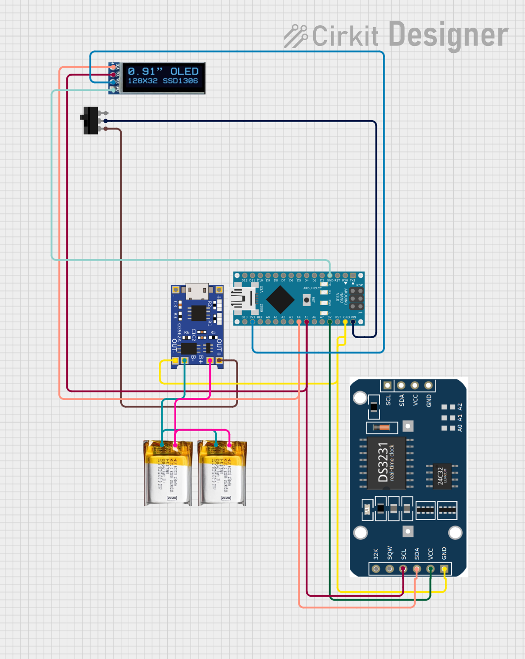
Explore Projects Built with SparkFun Nano Power Timer - TPL5110
Common Applications and Use Cases
- Intermittent data collection systems
- Battery-powered remote sensors
- Energy-saving devices
- Wildlife tracking and research tools
- IoT devices with periodic update requirements
Technical Specifications
The following table outlines the key technical details of the SparkFun Nano Power Timer - TPL5110:
| Specification | Value |
|---|---|
| Operating Voltage | 1.8V to 5.5V |
| Maximum Current | 20 mA (drive capability) |
| Timing Range | 100 ms to 7200 s (2 hours) |
| Timer Accuracy | ±1% |
| Quiescent Current | 35 nA (typical) |
| Interface | Digital (One-shot or continuous) |
| Operating Temperature | -40°C to 85°C |
Pin Configuration and Descriptions
| Pin Name | Description |
|---|---|
| GND | Ground connection |
| VIN | Input voltage (1.8V to 5.5V) |
| DRV | Drive output to control external MOSFET |
| DELAY | Delay setting input (resistor to GND sets the delay interval) |
| DONE | Signal input to indicate task completion |
Usage Instructions
How to Use the Component in a Circuit
- Power Connections: Connect the VIN pin to your power source (1.8V to 5.5V) and the GND pin to the ground.
- Delay Setting: Connect a resistor between the DELAY pin and GND to set the desired delay interval. The resistance value determines the delay time.
- Drive Output: Connect the DRV pin to the gate of an external N-channel MOSFET to control the power to your load.
- Signal Completion: Use the DONE pin to signal the TPL5110 that the task is complete, which will then turn off the power until the next cycle.
Important Considerations and Best Practices
- Ensure that the power supply voltage is within the specified range.
- Select a resistor for the DELAY pin that corresponds to the desired timing interval.
- Use a MOSFET with appropriate drive capability for your load.
- Avoid placing high inrush current loads directly on the DRV pin.
Example Code for Arduino UNO
// Example code to signal the TPL5110 that the task is complete using an Arduino UNO.

const int donePin = 7; // Connect this to the DONE pin on the TPL5110

void setup() {
  pinMode(donePin, OUTPUT);
  digitalWrite(donePin, LOW);
}

void loop() {
  // Perform your task here

  // Signal the TPL5110 that the task is complete
  digitalWrite(donePin, HIGH);
  delay(100); // Wait for a short period to ensure the signal is registered
  digitalWrite(donePin, LOW);

  // Enter a low-power state until the TPL5110 turns the power back on
  // Note: This requires additional code to reduce power consumption, which is
  // specific to the application and beyond the scope of this example.
}
Troubleshooting and FAQs
Common Issues
- Device not powering on: Check the power supply and connections to VIN and GND.
- Timer not functioning as expected: Verify the resistor value connected to the DELAY pin.
- Load not receiving power: Ensure the MOSFET is correctly connected and has sufficient drive capability.
Solutions and Tips for Troubleshooting
- Double-check all connections and ensure they are secure.
- Measure the voltage at the VIN pin to confirm power is being supplied.
- Use a multimeter to confirm the resistance value connected to the DELAY pin.
- If using the Arduino code, ensure the DONE pin is correctly defined and connected.
FAQs
Q: Can I use the TPL5110 to power down my entire project? A: Yes, the TPL5110 can control an external MOSFET to completely disconnect power to your project.
Q: How do I calculate the delay time based on the resistor value? A: The delay time is set by the resistor value according to the formula provided in the TPL5110 datasheet. SparkFun provides a delay time calculator on their product page.
Q: What is the maximum load current the TPL5110 can handle? A: The TPL5110 itself does not handle the load current directly. It drives an external MOSFET, and the current capability depends on the MOSFET's specifications.
Q: Is it possible to use the TPL5110 with a microcontroller other than an Arduino UNO? A: Yes, the TPL5110 can be used with any microcontroller capable of providing a digital signal to the DONE pin.