
How to Use Arduino Ethernet Shield (Rev3): Examples, Pinouts, and Specs
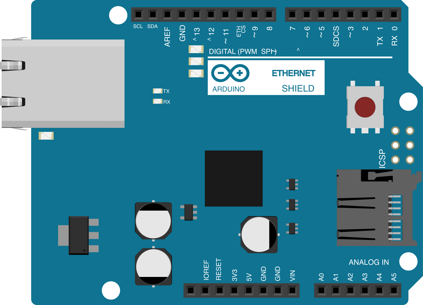
 Design with Arduino Ethernet Shield (Rev3) in Cirkit Designer
Introduction
The Arduino Ethernet Shield (Rev3) (Manufacturer Part ID: A000024) is an expansion board designed to provide Ethernet connectivity to Arduino boards. It allows an Arduino to connect to the internet or a local network, enabling communication with other devices and services. This shield is based on the Wiznet W5100 Ethernet chip, which supports both TCP and UDP protocols. It is compatible with most Arduino boards, including the Arduino UNO, Mega, and Leonardo.
Explore Projects Built with Arduino Ethernet Shield (Rev3)
 Open Project in Cirkit Designer
 Open Project in Cirkit Designer
 Open Project in Cirkit Designer
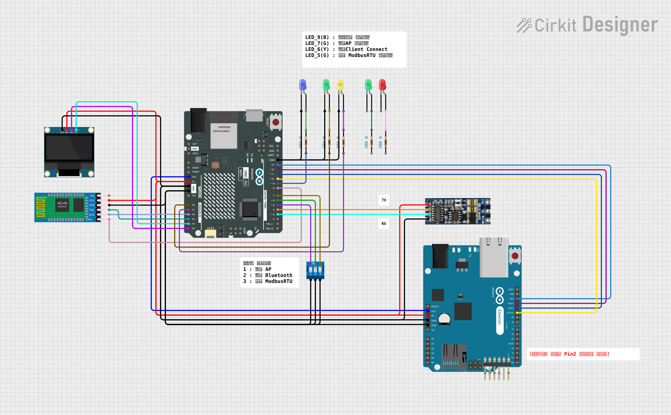 Open Project in Cirkit Designer
Explore Projects Built with Arduino Ethernet Shield (Rev3)
Open Project in Cirkit DesignerOpen Project in Cirkit DesignerOpen Project in Cirkit DesignerOpen Project in Cirkit DesignerCommon Applications and Use Cases
- IoT (Internet of Things) projects requiring network connectivity
- Remote monitoring and control of devices
- Data logging to a server or cloud service
- Home automation systems
- Web server hosting on an Arduino
Technical Specifications
Key Technical Details
- Ethernet Controller: Wiznet W5100
- Network Protocols Supported: TCP, UDP, IPv4
- Speed: 10/100 Mbps
- Operating Voltage: 5V (supplied by the Arduino board)
- Current Consumption: Approximately 180 mA
- Connector Type: RJ45 with integrated LEDs (link and activity indicators)
- MicroSD Card Slot: Supports FAT16 and FAT32 file systems
- Compatibility: Arduino UNO, Mega, Leonardo, and other boards with the same pinout
- Dimensions: 68.6 mm x 53.3 mm
Pin Configuration and Descriptions
The Arduino Ethernet Shield (Rev3) uses the following pins on the Arduino board:
| Pin | Function | Description |
|---|---|---|
| D10 | Ethernet Chip Select (CS) | Used to select the W5100 Ethernet controller. |
| D11 | SPI MOSI | Master Out Slave In - SPI data sent from Arduino to the W5100. |
| D12 | SPI MISO | Master In Slave Out - SPI data received from the W5100 to the Arduino. |
| D13 | SPI Clock (SCK) | Clock signal for SPI communication. |
| D4 | MicroSD Card Chip Select (CS) | Used to select the microSD card module. |
| D2 | Interrupt Pin (optional) | Can be used for advanced features like handling interrupts from the W5100. |
| 5V | Power Supply | Supplies power to the Ethernet Shield. |
| GND | Ground | Common ground connection. |
Usage Instructions
How to Use the Component in a Circuit
- Attach the Shield: Plug the Ethernet Shield (Rev3) onto your Arduino board. Ensure the pins are aligned correctly.
- Connect to a Network: Plug an Ethernet cable into the RJ45 connector on the shield and connect it to your router or switch.
- Power the Arduino: Supply power to the Arduino board via USB or an external power source.
- Install the Ethernet Library: Use the Arduino IDE to include the built-in
Ethernetlibrary. This library provides functions to initialize the shield, configure network settings, and send/receive data. - Upload Code: Write and upload a sketch to the Arduino board to enable network communication.
Example Code: Basic Web Server
The following example demonstrates how to set up a basic web server using the Ethernet Shield (Rev3):
#include <SPI.h>
#include <Ethernet.h>

// MAC address and IP address for the Ethernet Shield
byte mac[] = { 0xDE, 0xAD, 0xBE, 0xEF, 0xFE, 0xED };
IPAddress ip(192, 168, 1, 177); // Replace with your network's IP configuration

// Initialize the Ethernet server on port 80
EthernetServer server(80);

void setup() {
  // Start the Ethernet connection
  Ethernet.begin(mac, ip);

  // Start the server
  server.begin();

  // Print the IP address to the Serial Monitor
  Serial.begin(9600);
  Serial.print("Server is at ");
  Serial.println(Ethernet.localIP());
}

void loop() {
  // Listen for incoming clients
  EthernetClient client = server.available();
  if (client) {
    Serial.println("New client connected");
    boolean currentLineIsBlank = true;

    while (client.connected()) {
      if (client.available()) {
        char c = client.read();
        Serial.write(c);

        // If the client sends a blank line, send a response
        if (c == '\n' && currentLineIsBlank) {
          client.println("HTTP/1.1 200 OK");
          client.println("Content-Type: text/html");
          client.println("Connection: close");
          client.println();
          client.println("<!DOCTYPE HTML>");
          client.println("<html>");
          client.println("<h1>Welcome to Arduino Web Server!</h1>");
          client.println("</html>");
          break;
        }
        if (c == '\n') {
          currentLineIsBlank = true;
        } else if (c != '\r') {
          currentLineIsBlank = false;
        }
      }
    }
    // Give the client time to receive the data
    delay(1);
    client.stop();
    Serial.println("Client disconnected");
  }
}
Important Considerations and Best Practices
- Power Supply: Ensure the Arduino board is powered adequately, especially if additional peripherals are connected.
- Network Configuration: Use a static IP address or configure DHCP if your network supports it.
- MicroSD Card: If using the microSD card slot, ensure the card is formatted as FAT16 or FAT32.
- Avoid Pin Conflicts: Be mindful of pin usage, especially if other shields or modules are used in the project.
Troubleshooting and FAQs
Common Issues and Solutions
Ethernet Shield Not Detected:
- Ensure the shield is properly seated on the Arduino board.
- Verify that the
Ethernetlibrary is included in your sketch. - Check the MAC and IP address configuration.
No Network Connectivity:
- Confirm the Ethernet cable is securely connected.
- Test the cable and network port with another device.
- Verify the IP address is within the range of your network.
MicroSD Card Not Working:
- Ensure the card is formatted as FAT16 or FAT32.
- Check that the card is inserted correctly.
- Use the
SDlibrary to test the card independently.
Slow or Unstable Connection:
- Reduce the amount of data being sent or received.
- Check for network congestion or interference.
FAQs
Q: Can I use the Ethernet Shield with an Arduino Nano?
A: The Ethernet Shield (Rev3) is designed for full-size Arduino boards like the UNO and Mega. For smaller boards like the Nano, consider using an Ethernet module instead.
Q: Does the shield support PoE (Power over Ethernet)?
A: No, the standard Ethernet Shield (Rev3) does not support PoE. However, a PoE module can be added separately.
Q: Can I use the Ethernet Shield and Wi-Fi simultaneously?
A: Yes, but you must ensure there are no pin conflicts and manage the network interfaces in your code.
Q: What is the maximum length of the Ethernet cable?
A: The shield supports standard Ethernet cable lengths of up to 100 meters (328 feet).