Cirkit Designer Logo
Cirkit Designer
Your all-in-one circuit design IDE
Home / 
Component Documentation

How to Use VL53L8CX Time-of-Flight 8×8-Zone Distance Sensor Carrier with Voltage Regulators: Examples, Pinouts, and Specs

Image of VL53L8CX Time-of-Flight 8×8-Zone Distance Sensor Carrier with Voltage Regulators
Cirkit Designer LogoDesign with VL53L8CX Time-of-Flight 8×8-Zone Distance Sensor Carrier with Voltage Regulators in Cirkit Designer

Introduction

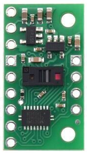
The VL53L8CX Time-of-Flight (ToF) sensor by Pololu is an advanced laser-ranging module that is capable of measuring distances by timing the delay of a light signal as it reflects off a surface and returns to the sensor. This particular model features an 8×8 zone detection grid, allowing for spatial resolution in the measurements it provides. It is equipped with voltage regulators, making it robust against power supply variations. Common applications include robotics for obstacle detection, user presence detection in smart devices, and general-purpose proximity sensing.

Explore Projects Built with VL53L8CX Time-of-Flight 8×8-Zone Distance Sensor Carrier with Voltage Regulators

Use Cirkit Designer to design, explore, and prototype these projects online. Some projects support real-time simulation. Click "Open Project" to start designing instantly!
A-Star 32U4 Mini Controlled Servo with VL53L8CX Time-of-Flight Distance Sensing
Image of Servo con distance sensor: A project utilizing VL53L8CX Time-of-Flight 8×8-Zone Distance Sensor Carrier with Voltage Regulators in a practical application
This circuit features an A-Star 32U4 Mini microcontroller connected to a VL53L8CX Time-of-Flight distance sensor and a servo motor. The microcontroller powers both the sensor and the servo, and it is configured to communicate with the sensor via I2C (using pins 2 and 3 for SDA and SCL, respectively) and to control the servo via a PWM signal on pin 10. The purpose of the circuit is likely to measure distances and respond with movements of the servo based on the sensor readings.
Cirkit Designer LogoOpen Project in Cirkit Designer
ESP8266 NodeMCU-Based Smart Eye Pressure Monitor with OLED Display and Wi-Fi Connectivity
Image of Copy of test 2 (7): A project utilizing VL53L8CX Time-of-Flight 8×8-Zone Distance Sensor Carrier with Voltage Regulators in a practical application
This circuit features an ESP8266 NodeMCU microcontroller interfaced with a VL53L0X time-of-flight distance sensor, a 0.96" OLED display, a piezo sensor, and a photodiode for light detection. The ESP8266 collects data from the sensors, displays readings on the OLED, and hosts a web server to present the information. It is likely designed for distance measurement, light intensity detection, and pressure sensing, with the capability to monitor and display these parameters in real-time over WiFi.
Cirkit Designer LogoOpen Project in Cirkit Designer
Cellular-Enabled IoT Device with Real-Time Clock and Power Management
Image of LRCM PHASE 2 BASIC: A project utilizing VL53L8CX Time-of-Flight 8×8-Zone Distance Sensor Carrier with Voltage Regulators in a practical application
This circuit features a LilyGo-SIM7000G module for cellular communication and GPS functionality, interfaced with an RTC DS3231 for real-time clock capabilities. It includes voltage sensing through two voltage sensor modules, and uses an 8-channel opto-coupler for isolating different parts of the circuit. Power management is handled by a buck converter connected to a DC power source and batteries, with a fuse for protection and a rocker switch for on/off control. Additionally, there's an LED for indication purposes.
Cirkit Designer LogoOpen Project in Cirkit Designer
Arduino UNO with A9G GSM/GPRS and Dual VL53L1X Distance Sensors
Image of TED CIRCUIT : A project utilizing VL53L8CX Time-of-Flight 8×8-Zone Distance Sensor Carrier with Voltage Regulators in a practical application
This circuit features an Arduino UNO microcontroller interfaced with an A9G GSM/GPRS+GPS/BDS module and two VL53L1X time-of-flight distance sensors. The A9G module is connected to the Arduino via serial communication for GPS and GSM functionalities, while both VL53L1X sensors are connected through I2C with shared SDA and SCL lines and individual SHUT pins for selective sensor activation. The Arduino is programmed to control these peripherals, although the specific functionality is not detailed in the provided code.
Cirkit Designer LogoOpen Project in Cirkit Designer

Explore Projects Built with VL53L8CX Time-of-Flight 8×8-Zone Distance Sensor Carrier with Voltage Regulators

Use Cirkit Designer to design, explore, and prototype these projects online. Some projects support real-time simulation. Click "Open Project" to start designing instantly!
Image of Servo con distance sensor: A project utilizing VL53L8CX Time-of-Flight 8×8-Zone Distance Sensor Carrier with Voltage Regulators in a practical application
A-Star 32U4 Mini Controlled Servo with VL53L8CX Time-of-Flight Distance Sensing
This circuit features an A-Star 32U4 Mini microcontroller connected to a VL53L8CX Time-of-Flight distance sensor and a servo motor. The microcontroller powers both the sensor and the servo, and it is configured to communicate with the sensor via I2C (using pins 2 and 3 for SDA and SCL, respectively) and to control the servo via a PWM signal on pin 10. The purpose of the circuit is likely to measure distances and respond with movements of the servo based on the sensor readings.
Cirkit Designer LogoOpen Project in Cirkit Designer
Image of Copy of test 2 (7): A project utilizing VL53L8CX Time-of-Flight 8×8-Zone Distance Sensor Carrier with Voltage Regulators in a practical application
ESP8266 NodeMCU-Based Smart Eye Pressure Monitor with OLED Display and Wi-Fi Connectivity
This circuit features an ESP8266 NodeMCU microcontroller interfaced with a VL53L0X time-of-flight distance sensor, a 0.96" OLED display, a piezo sensor, and a photodiode for light detection. The ESP8266 collects data from the sensors, displays readings on the OLED, and hosts a web server to present the information. It is likely designed for distance measurement, light intensity detection, and pressure sensing, with the capability to monitor and display these parameters in real-time over WiFi.
Cirkit Designer LogoOpen Project in Cirkit Designer
Image of LRCM PHASE 2 BASIC: A project utilizing VL53L8CX Time-of-Flight 8×8-Zone Distance Sensor Carrier with Voltage Regulators in a practical application
Cellular-Enabled IoT Device with Real-Time Clock and Power Management
This circuit features a LilyGo-SIM7000G module for cellular communication and GPS functionality, interfaced with an RTC DS3231 for real-time clock capabilities. It includes voltage sensing through two voltage sensor modules, and uses an 8-channel opto-coupler for isolating different parts of the circuit. Power management is handled by a buck converter connected to a DC power source and batteries, with a fuse for protection and a rocker switch for on/off control. Additionally, there's an LED for indication purposes.
Cirkit Designer LogoOpen Project in Cirkit Designer
Image of TED CIRCUIT : A project utilizing VL53L8CX Time-of-Flight 8×8-Zone Distance Sensor Carrier with Voltage Regulators in a practical application
Arduino UNO with A9G GSM/GPRS and Dual VL53L1X Distance Sensors
This circuit features an Arduino UNO microcontroller interfaced with an A9G GSM/GPRS+GPS/BDS module and two VL53L1X time-of-flight distance sensors. The A9G module is connected to the Arduino via serial communication for GPS and GSM functionalities, while both VL53L1X sensors are connected through I2C with shared SDA and SCL lines and individual SHUT pins for selective sensor activation. The Arduino is programmed to control these peripherals, although the specific functionality is not detailed in the provided code.
Cirkit Designer LogoOpen Project in Cirkit Designer

Technical Specifications

Key Features

  • Resolution: 8×8 zone grid
  • Maximum Range: Up to 4 meters
  • Minimum Range: 4 cm
  • Interface: I2C
  • Supply Voltage: 2.6 V to 3.5 V
  • Emitter: 940 nm VCSEL (Vertical Cavity Surface Emitting Laser)
  • Field of View: 63° diagonal

Pin Configuration and Descriptions

Pin Number Name Description
1 VDD Power supply (2.6 V to 3.5 V)
2 GND Ground connection
3 SDA I2C Data Line
4 SCL I2C Clock Line
5 GPIO1 Programmable interrupt output
6 XSHUT Shutdown pin (active low)

Usage Instructions

Integration into a Circuit

  1. Power Supply: Connect the VDD pin to a stable 2.6 V to 3.5 V power source. Ensure that the GND pin is connected to the common ground in your circuit.
  2. I2C Communication: Connect the SDA and SCL pins to the corresponding I2C data and clock lines on your microcontroller.
  3. Interrupts (Optional): The GPIO1 pin can be used to configure interrupts for data-ready events.
  4. Shutdown Control (Optional): The XSHUT pin can be used to put the sensor into a low-power state when driven low.

Best Practices

  • Ensure that the sensor has a clear line of sight to the target for accurate measurements.
  • Avoid exposing the sensor to direct sunlight or other strong light sources that could interfere with the measurements.
  • Use pull-up resistors on the I2C lines if they are not already present on your microcontroller board.

Example Code for Arduino UNO

#include <Wire.h>

// VL53L8CX default I2C address
#define SENSOR_ADDRESS 0x29

void setup() {
  Wire.begin(); // Initialize I2C
  Serial.begin(9600); // Start serial communication at 9600 baud

  // Configure sensor settings as needed
  // ...
}

void loop() {
  // Trigger a distance measurement
  // ...

  // Read measurement result
  // ...

  // Print the result to the Serial Monitor
  Serial.print("Distance: ");
  Serial.print(distance);
  Serial.println(" mm");

  delay(1000); // Wait for 1 second before next measurement
}

Note: This example code is a template to get started. Specific functions to configure the sensor and read measurements need to be implemented based on the sensor's datasheet and library functions.

Troubleshooting and FAQs

Common Issues

  • No Data: Ensure that the sensor is correctly powered and that the I2C connections are secure.
  • Inaccurate Readings: Check for obstructions in front of the sensor and avoid reflective surfaces near the target area.
  • Intermittent Operation: Verify that the voltage supply is within the specified range and stable.

FAQs

Q: Can the sensor measure distances through glass or transparent materials? A: No, the sensor cannot measure through transparent materials as the light will either pass through or reflect off the surface.

Q: What is the maximum I2C speed supported by the sensor? A: The VL53L8CX supports I2C speeds up to 400 kHz (Fast Mode).

Q: How can I change the I2C address of the sensor? A: The I2C address can be changed by writing to the I2C address register. Refer to the sensor's datasheet for the specific procedure.

Q: Is the sensor suitable for outdoor use? A: The sensor is designed for indoor use. Outdoor conditions such as direct sunlight may affect its performance.

For further assistance, consult the sensor's datasheet and the manufacturer's technical support resources.