
How to Use DAC PCM5102: Examples, Pinouts, and Specs
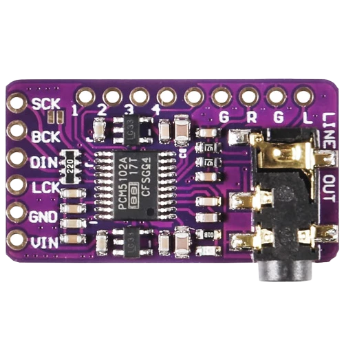
 Design with DAC PCM5102 in Cirkit Designer
Introduction
The PCM5102 is a high-performance digital-to-analog converter (DAC) designed for audio applications. It is capable of converting digital audio signals into high-quality analog audio output with low distortion and high resolution. This makes it an ideal choice for high-fidelity sound reproduction in devices such as audio players, home theater systems, and professional audio equipment.
Explore Projects Built with DAC PCM5102
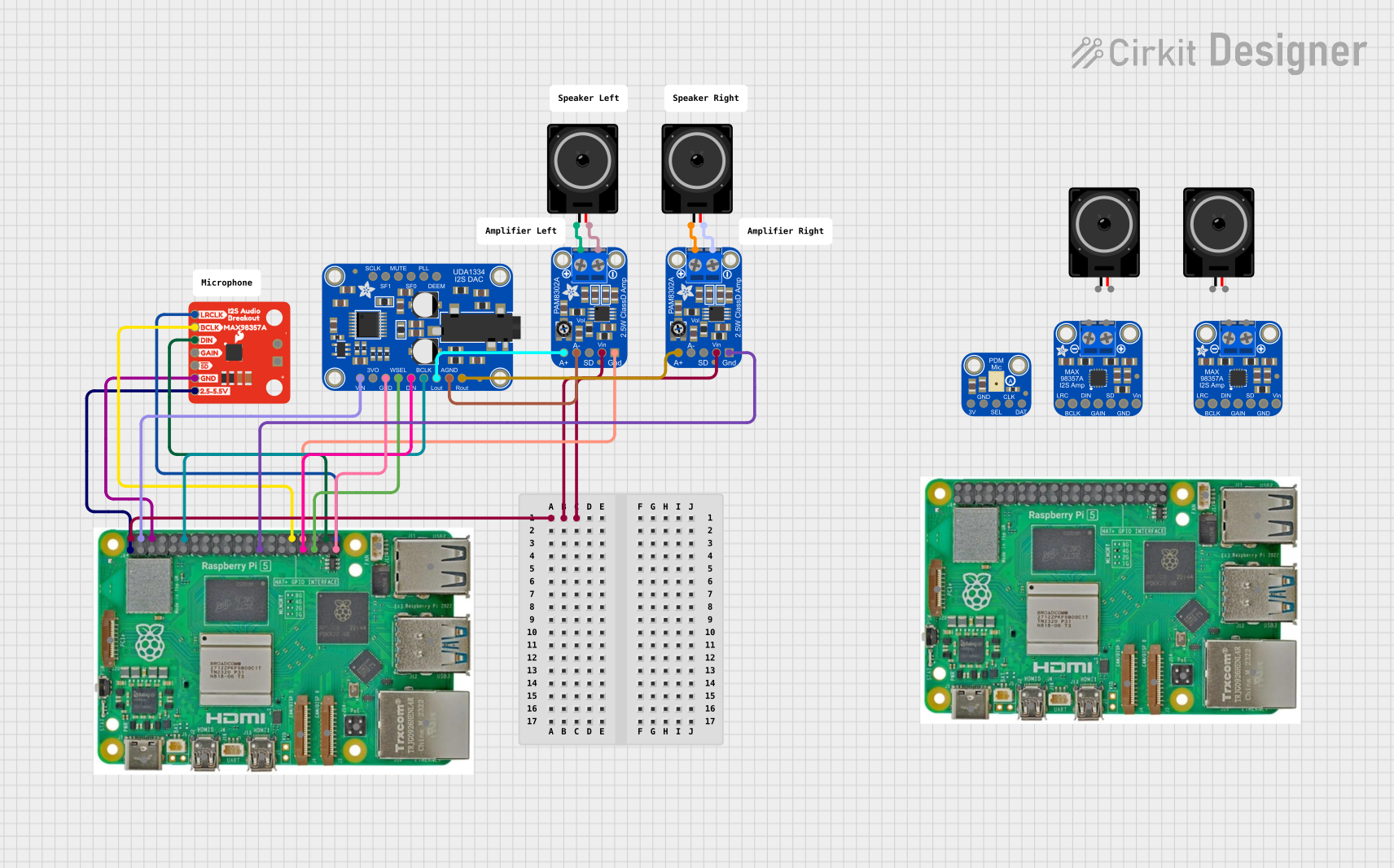 Open Project in Cirkit Designer
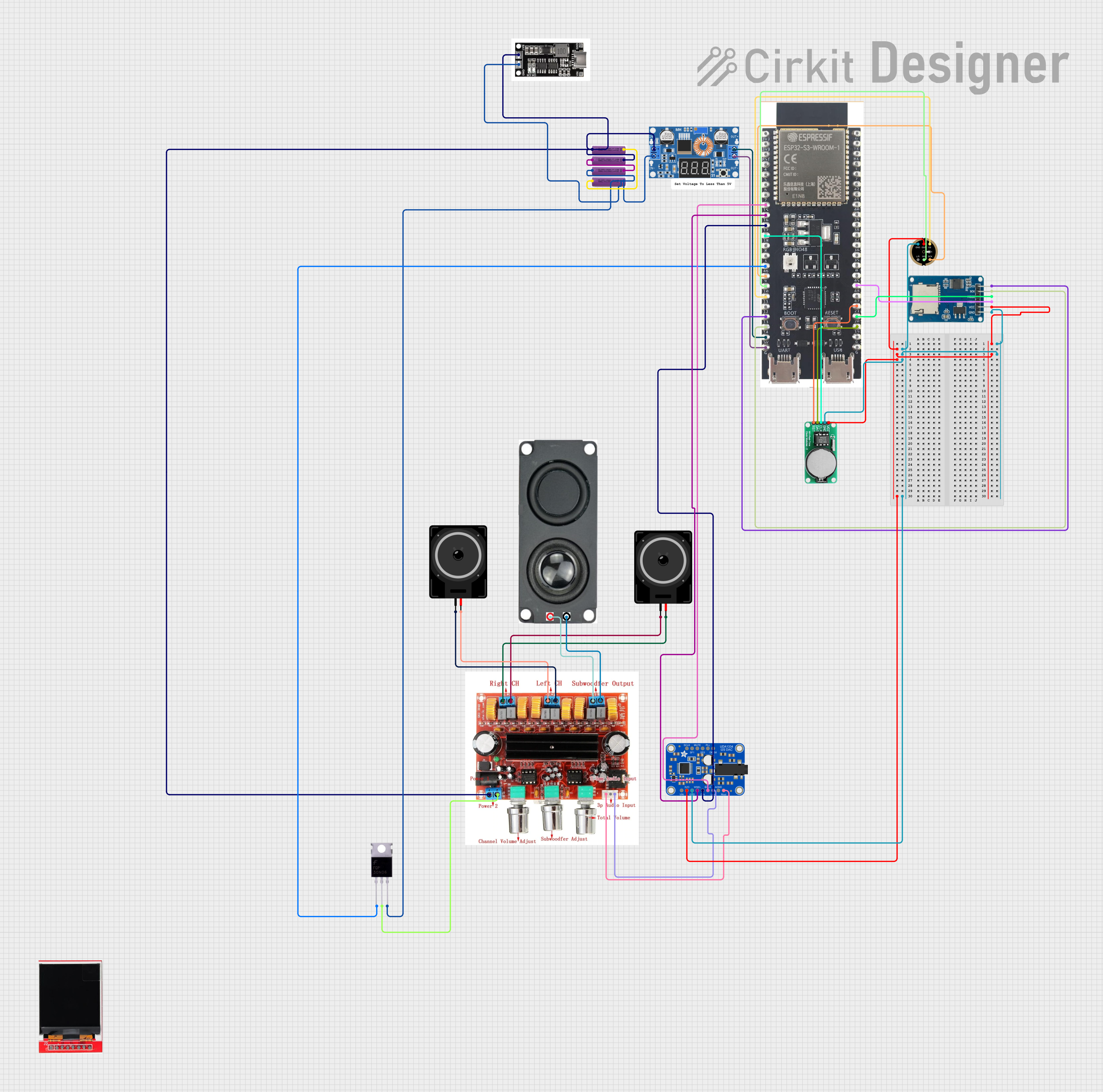 Open Project in Cirkit Designer
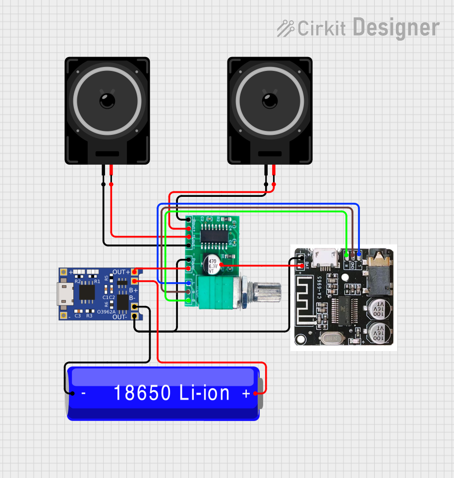 Open Project in Cirkit Designer
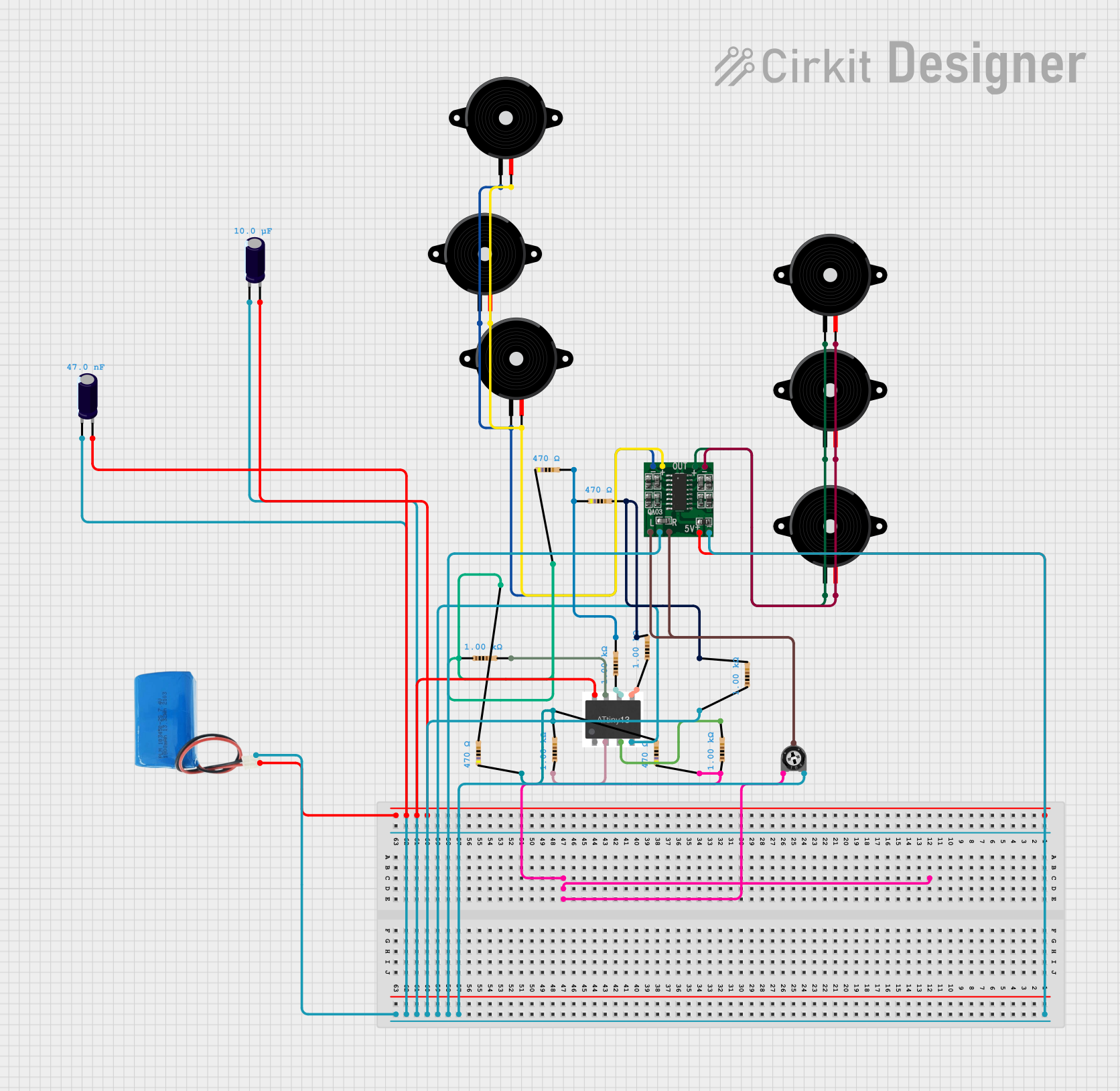 Open Project in Cirkit Designer
Explore Projects Built with DAC PCM5102
Open Project in Cirkit DesignerOpen Project in Cirkit DesignerOpen Project in Cirkit DesignerOpen Project in Cirkit DesignerCommon Applications and Use Cases
- High-fidelity audio systems
- Digital audio players (DAPs)
- Home theater systems
- Audio signal processing
- Professional audio equipment
- DIY audio projects
Technical Specifications
The PCM5102 DAC is designed to deliver exceptional audio performance with a range of advanced features. Below are its key technical specifications:
Key Technical Details
- Supply Voltage (VDD): 3.3V
- Digital Input Voltage: 1.8V to 3.3V logic levels
- Output Voltage (RMS): 2.1V (typical)
- Signal-to-Noise Ratio (SNR): 112 dB
- Total Harmonic Distortion + Noise (THD+N): -93 dB
- Sampling Rates Supported: 8 kHz to 384 kHz
- Audio Data Formats: I2S, Left-Justified, Right-Justified
- Power Consumption: Low-power operation with 20 mW typical consumption
- Operating Temperature Range: -25°C to +85°C
Pin Configuration and Descriptions
The PCM5102 is typically available in a 20-pin TSSOP package. Below is the pin configuration and description:
| Pin Number | Pin Name | Description |
|---|---|---|
| 1 | DVDD | Digital power supply (3.3V) |
| 2 | DGND | Digital ground |
| 3 | LRCK | Left/Right clock input for I2S |
| 4 | BCK | Bit clock input for I2S |
| 5 | DIN | Digital audio data input |
| 6 | SCK | System clock input (optional) |
| 7 | FMT | Audio format selection (I2S, LJ, RJ) |
| 8 | XSMT | Soft mute control |
| 9 | FLT | Filter selection (sharp/slow roll-off) |
| 10 | VCOM | Common-mode voltage output |
| 11 | VOUTL | Left-channel analog audio output |
| 12 | VOUTR | Right-channel analog audio output |
| 13 | AGND | Analog ground |
| 14 | AVDD | Analog power supply (3.3V) |
| 15 | NC | No connection |
| 16 | NC | No connection |
| 17 | NC | No connection |
| 18 | NC | No connection |
| 19 | NC | No connection |
| 20 | NC | No connection |
Usage Instructions
How to Use the PCM5102 in a Circuit
Power Supply:
- Connect the DVDD and AVDD pins to a stable 3.3V power supply.
- Ensure proper decoupling capacitors (e.g., 0.1 µF and 10 µF) are placed close to the power pins to reduce noise.
Grounding:
- Connect DGND and AGND to a common ground plane to minimize noise interference.
Digital Audio Input:
- Use the DIN, LRCK, and BCK pins to provide the digital audio signal in I2S, Left-Justified, or Right-Justified format.
- If using I2S, ensure the LRCK frequency matches the sampling rate of the audio signal.
Analog Audio Output:
- Connect the VOUTL and VOUTR pins to the left and right audio output channels, respectively.
- Use appropriate filtering capacitors to remove high-frequency noise from the output.
Audio Format Selection:
- Use the FMT pin to select the desired audio format:
- I2S: Connect FMT to ground.
- Left-Justified: Connect FMT to DVDD.
- Right-Justified: Leave FMT floating.
- Use the FMT pin to select the desired audio format:
Filter Selection:
- Use the FLT pin to select the desired digital filter:
- Sharp Roll-Off: Connect FLT to ground.
- Slow Roll-Off: Connect FLT to DVDD.
- Use the FLT pin to select the desired digital filter:
Soft Mute:
- Use the XSMT pin to enable or disable soft mute:
- Mute Enabled: Connect XSMT to ground.
- Mute Disabled: Connect XSMT to DVDD.
- Use the XSMT pin to enable or disable soft mute:
Important Considerations and Best Practices
- Ensure the digital and analog grounds are properly connected to avoid ground loops.
- Use high-quality decoupling capacitors to minimize power supply noise.
- Avoid long traces for the I2S signals to reduce signal degradation and jitter.
- If using an external clock, ensure the SCK frequency is an integer multiple of the sampling rate.
Example: Connecting PCM5102 to Arduino UNO
The PCM5102 can be interfaced with an Arduino UNO using the I2S protocol. Below is an example code snippet to output audio data:
#include <I2S.h> // Include the I2S library for Arduino

void setup() {
  // Initialize I2S with 44.1 kHz sampling rate and 16-bit resolution
  if (!I2S.begin(I2S_PHILIPS_MODE, 44100, 16)) {
    // Check if I2S initialization failed
    while (1) {
      // Halt the program if initialization fails
    }
  }
}

void loop() {
  // Generate a simple sine wave for testing
  for (int i = 0; i < 360; i++) {
    // Calculate the sine wave value
    int16_t sample = 32767 * sin(i * PI / 180);
    // Write the sample to the I2S output
    I2S.write(sample);
  }
}
Note: The Arduino UNO requires an I2S-compatible shield or module to interface with the PCM5102, as the UNO does not natively support I2S.
Troubleshooting and FAQs
Common Issues and Solutions
No Audio Output:
- Verify that the power supply is stable and properly connected to DVDD and AVDD.
- Check the I2S connections (DIN, LRCK, BCK) for proper wiring.
- Ensure the audio format selected on the FMT pin matches the input signal format.
Distorted Audio:
- Check the sampling rate and bit depth of the input signal.
- Ensure proper grounding and minimize noise on the power supply lines.
- Verify that the analog output is properly filtered.
High Noise or Hissing Sound:
- Use high-quality decoupling capacitors close to the power pins.
- Ensure the FLT pin is configured correctly for the desired filter type.
PCM5102 Overheating:
- Verify that the supply voltage does not exceed 3.3V.
- Check for short circuits or incorrect connections.
FAQs
Q: Can the PCM5102 operate at 5V?
A: No, the PCM5102 is designed to operate at a maximum supply voltage of 3.3V. Exceeding this voltage may damage the component.
Q: What is the maximum sampling rate supported by the PCM5102?
A: The PCM5102 supports sampling rates up to 384 kHz.
Q: Can I use the PCM5102 with a Raspberry Pi?
A: Yes, the PCM5102 can be interfaced with a Raspberry Pi using the I2S protocol.
Q: How do I select the audio format for the PCM5102?
A: Use the FMT pin to select the desired format (I2S, Left-Justified, or Right-Justified) as described in the usage instructions.
Q: Is an external clock required for the PCM5102?
A: No, the PCM5102 has an internal PLL that can generate the required clock from the I2S signals. However, an external clock can be used if desired.